HP Notebook 100 Compaq Armada 100S and Notebook 100 Series Maintenance and Ser - Page 89
System Board, IMPORTANT
 |
View all HP Notebook 100 manuals
Add to My Manuals
Save this manual to your list of manuals |
Page 89 highlights
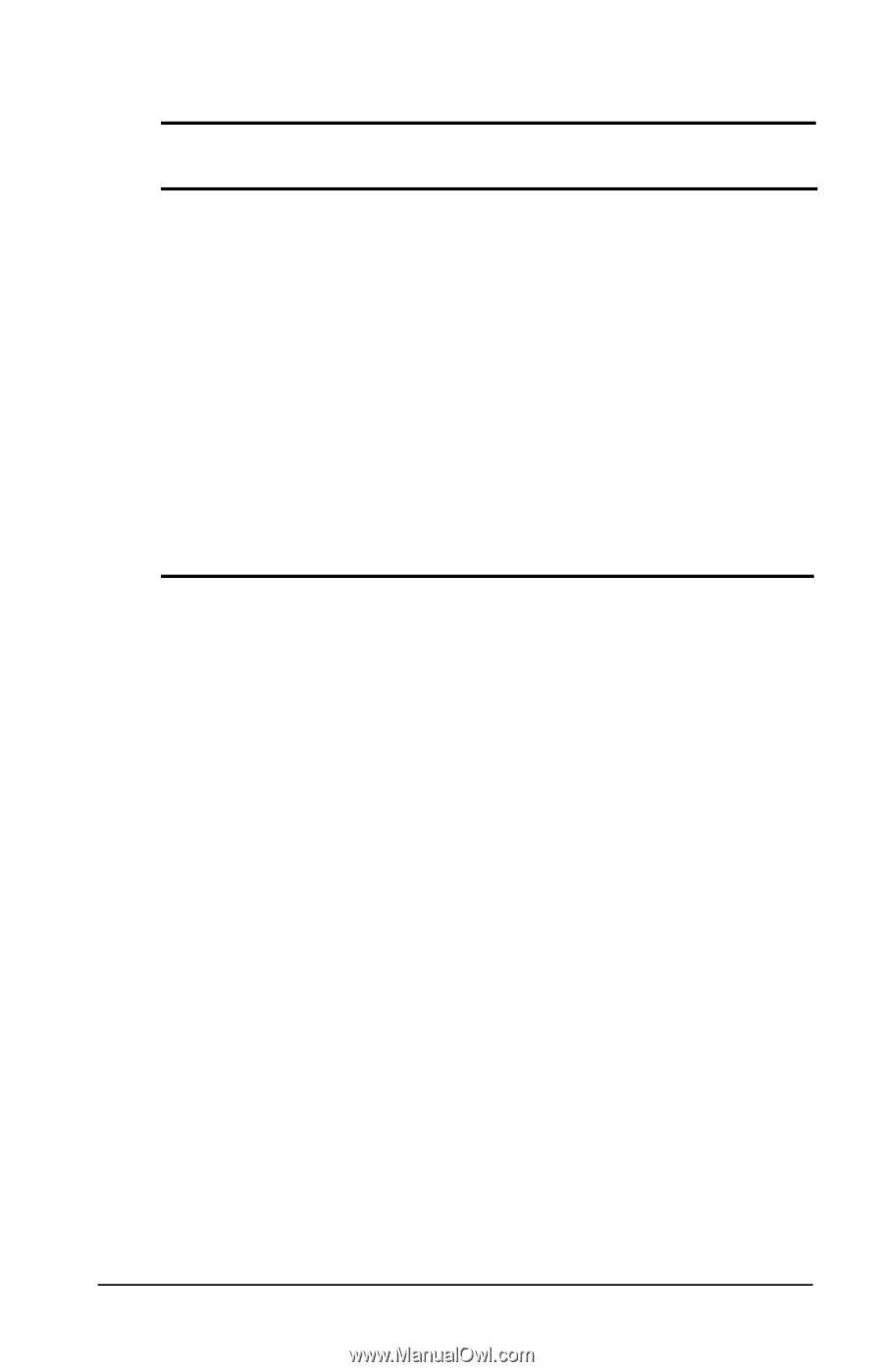
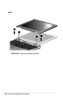
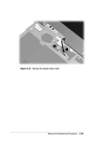
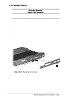
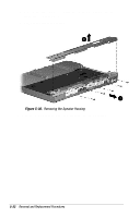
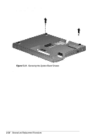
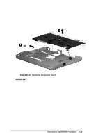
5.19 System Board System Board Spare Part Numbers 64 MB SDRAM (used only with config. codes beginning with "FQ5" and "FQ6") 64 MB SDRAM (used only with config. codes "FQ45", "FQ47", and "FQ48") 64 MB SDRAM (used only with config. codes "FFG1" through "FFG4") 64 MB SDRAM (used only with config. codes "FFF5" and "FFF6") 32 MB SDRAM (used only with config. codes "FQ41" through "FQ44") 32 MB SDRAM (used only with config. codes "FFF1" through "FFF4) RJ11 cover (spared with Plastics Kit) PC Card door (spared with Plastics Kit) 207657-001 207656-001 189047-001 176035-001 207655-001 176034-001 176048-001 176048-001 IMPORTANT: When replacing the system board, it is imperative that the DIP switches be set correctly. Refer to Section 5.17 for information on setting the display DIP switches. 1. Prepare the computer for disassembly (Section 5.3) and, in the order below, remove the following components: s Top cover (Section 5.10) s Hard drive (Section 5.11) s RTC battery (Section 5.12) s Keyboard (Section 5.13) s EMI shield (Section 5.14) s TouchPad (Section 5.15) s Speakers (Section 5.16) s Display assembly (Section 5.17) s Speaker housing (Section 5.18) 2. Turn the computer bottom side up with the rear panel facing forward. Removal and Replacement Procedures 5-33
-
 1
1 -
2
-
3
-
4
-
5
-
6
-
7
-
8
-
9
-
10
-
11
-
12
-
13
-
14
-
15
-
16
-
17
-
18
-
19
-
20
-
21
-
22
-
23
-
24
-
25
-
26
-
27
-
28
-
29
-
30
-
31
-
32
-
33
-
34
-
35
-
36
-
37
-
38
-
39
-
40
-
41
-
42
-
43
-
44
-
45
-
46
-
47
-
48
-
49
-
50
-
51
-
52
-
53
-
54
-
55
-
56
-
57
-
58
-
59
-
60
-
61
-
62
-
63
-
64
-
65
-
66
-
67
-
68
-
69
-
70
-
71
-
72
-
73
-
74
-
75
-
76
-
77
-
78
-
79
-
80
-
81
-
82
-
83
-
 84
84 -
 85
85 -
 86
86 -
 87
87 -
 88
88 -
 89
89 -
 90
90 -
 91
91 -
 92
92 -
 93
93 -
 94
94 -
95
-
96
-
97
-
98
-
99
-
100
-
101
-
102
-
103
-
104
-
105
-
106
-
107
-
108
-
109
-
110
 |
 |