HP Pavilion TouchSmart 14z-n100 HP Pavilion 14 Notebook PC HP Pavilion TouchSm - Page 18
Left side
 |
View all HP Pavilion TouchSmart 14z-n100 manuals
Add to My Manuals
Save this manual to your list of manuals |
Page 18 highlights
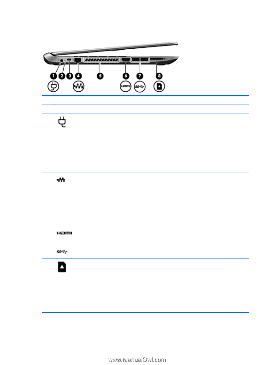
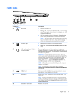
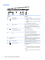
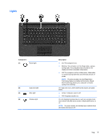
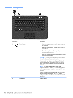
Left side Component (1) (2) Power connector AC adapter light (3) Security cable slot (4) RJ-45 (network) jack RJ-45 (network) status lights (2) (5) Vent (6) HDMI port (7) USB 3.0 ports (2) (8) Memory card reader Description Connects an AC adapter. ● White: The AC adapter is connected and the battery is charged. ● Amber: The AC adapter is connected and the battery is charging. ● Off: The computer is using DC power. Attaches an optional security cable to the computer. NOTE: The security cable is designed to act as a deterrent, but it may not prevent the computer from being mishandled or stolen. Connects a network cable. White: The network is connected. Amber: Activity is occurring on the network. Enable airflow to cool internal components. NOTE: The computer fan starts up automatically to cool internal components and prevent overheating. It is normal for the internal fan to cycle on and off during routine operation. Connects an optional video or audio device, such as a high-definition television, any compatible digital or audio component, or a high-speed HDMI device. Connect optional USB device, such as a keyboard, mouse, external drive, printer, scanner or USB hub. Reads data from and writes data to memory cards such as Secure Digital (SD). To insert: 1. Hold the card, label side up, with connectors facing the slot and push in the card until it is firmly seated. To remove: 1. Press in on the card and quickly release it until it pops out. 8 Chapter 2 External component identification
-
 1
1 -
2
-
3
-
4
-
5
-
6
-
7
-
8
-
9
-
10
-
11
-
12
-
 13
13 -
 14
14 -
 15
15 -
 16
16 -
 17
17 -
 18
18 -
 19
19 -
 20
20 -
 21
21 -
 22
22 -
 23
23 -
24
-
25
-
26
-
27
-
28
-
29
-
30
-
31
-
32
-
33
-
34
-
35
-
36
-
37
-
38
-
39
-
40
-
41
-
42
-
43
-
44
-
45
-
46
-
47
-
48
-
49
-
50
-
51
-
52
-
53
-
54
-
55
-
56
-
57
-
58
-
59
-
60
-
61
-
62
-
63
-
64
-
65
-
66
-
67
-
68
-
69
-
70
-
71
-
72
-
73
-
74
-
75
-
76
-
77
-
78
-
79
-
80
-
81
-
82
-
83
-
84
-
85
-
86
-
87
-
88
-
89
-
90
-
91
-
92
-
93
-
94
-
95
-
96
-
97
-
98
-
99
-
100
-
101
-
102
-
103
-
104
-
105
-
106
-
107
-
108
-
109
-
110
-
111
-
112
-
113
-
114
-
115
-
116
-
117
-
118
-
119
-
120
-
121
-
122
-
123
-
124
-
125
-
126
-
127
-
128
-
129
-
130
 |
 |