HP Pavilion dv4-1100 HP Pavilion dv4 Entertainment PC - Maintenance and Servic - Page 74
by pulling the module away from the slot at an angle., to prevent incorrect insertion.
 |
View all HP Pavilion dv4-1100 manuals
Add to My Manuals
Save this manual to your list of manuals |
Page 74 highlights
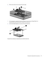
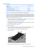
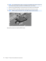
NOTE: The red WWAN antenna cable is connected to the WWAN module "Main" terminal. The blue WWAN antenna cable is connected to the WWAN module "Aux" terminal. 5. Remove the two Phillips PM2.0×4.0 screws that secure the module to the computer (2). 6. Remove the WWAN module (3) by pulling the module away from the slot at an angle. NOTE: WWAN modules are designed with a notch (4) to prevent incorrect insertion. Reverse this procedure to install the WWAN module. 66 Chapter 4 Removal and replacement procedures
-
 1
1 -
2
-
3
-
4
-
5
-
6
-
7
-
8
-
9
-
10
-
11
-
12
-
13
-
14
-
15
-
16
-
17
-
18
-
19
-
20
-
21
-
22
-
23
-
24
-
25
-
26
-
27
-
28
-
29
-
30
-
31
-
32
-
33
-
34
-
35
-
36
-
37
-
38
-
39
-
40
-
41
-
42
-
43
-
44
-
45
-
46
-
47
-
48
-
49
-
50
-
51
-
52
-
53
-
54
-
55
-
56
-
57
-
58
-
59
-
60
-
61
-
62
-
63
-
64
-
65
-
66
-
67
-
68
-
 69
69 -
 70
70 -
 71
71 -
 72
72 -
 73
73 -
 74
74 -
 75
75 -
 76
76 -
 77
77 -
 78
78 -
 79
79 -
80
-
81
-
82
-
83
-
84
-
85
-
86
-
87
-
88
-
89
-
90
-
91
-
92
-
93
-
94
-
95
-
96
-
97
-
98
-
99
-
100
-
101
-
102
-
103
-
104
-
105
-
106
-
107
-
108
-
109
-
110
-
111
-
112
-
113
-
114
-
115
-
116
-
117
-
118
-
119
-
120
-
121
-
122
-
123
-
124
-
125
-
126
-
127
-
128
-
129
-
130
-
131
-
132
-
133
-
134
-
135
-
136
-
137
-
138
-
139
-
140
-
141
-
142
-
143
-
144
-
145
-
146
-
147
-
148
-
149
-
150
-
151
-
152
-
153
-
154
-
155
-
156
-
157
-
158
-
159
-
160
-
161
-
162
-
163
-
164
-
165
-
166
-
167
-
168
-
169
-
170
-
171
-
172
-
173
-
174
-
175
-
176
-
177
-
178
-
179
-
180
-
181
-
182
-
183
-
184
-
185
-
186
-
187
-
188
-
189
-
190
-
191
-
192
-
193
-
194
-
195
-
196
-
197
-
198
-
199
-
200
-
201
-
202
 |
 |
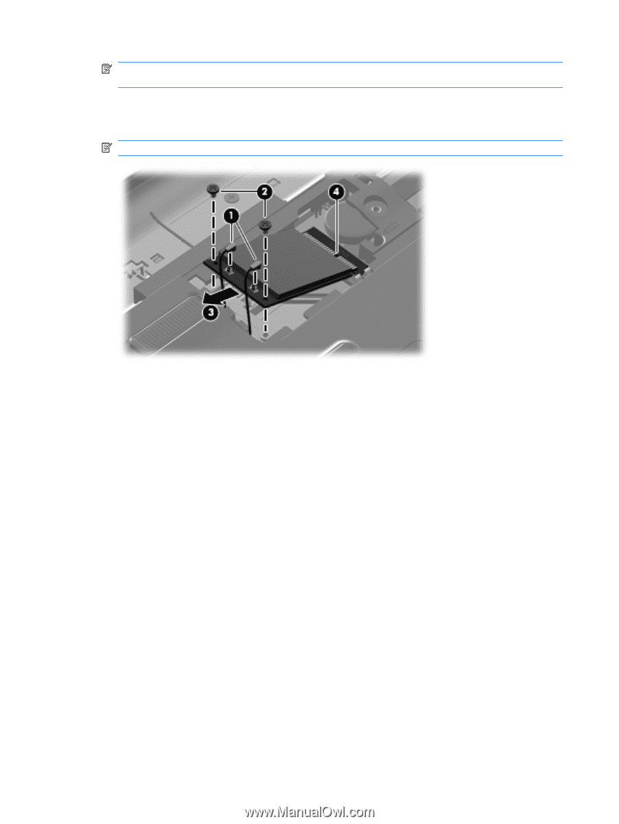
NOTE:
The red WWAN antenna cable is connected to the WWAN module “Main” terminal. The
blue WWAN antenna cable is connected to the WWAN module “Aux” terminal.
5.
Remove the two Phillips PM2.0×4.0 screws that secure the module to the computer
(2)
.
6.
Remove the WWAN module
(3)
by pulling the module away from the slot at an angle.
NOTE:
WWAN modules are designed with a notch
(4)
to prevent incorrect insertion.
Reverse this procedure to install the WWAN module.
66
Chapter 4
Removal and replacement procedures