HP Pavilion dv7-2100 HP Pavilion dv7 Entertainment PC - Maintenance and Servic - Page 74
Four Phillips PM2.5×7.0 screws., through the hinge channel.
 |
View all HP Pavilion dv7-2100 manuals
Add to My Manuals
Save this manual to your list of manuals |
Page 74 highlights
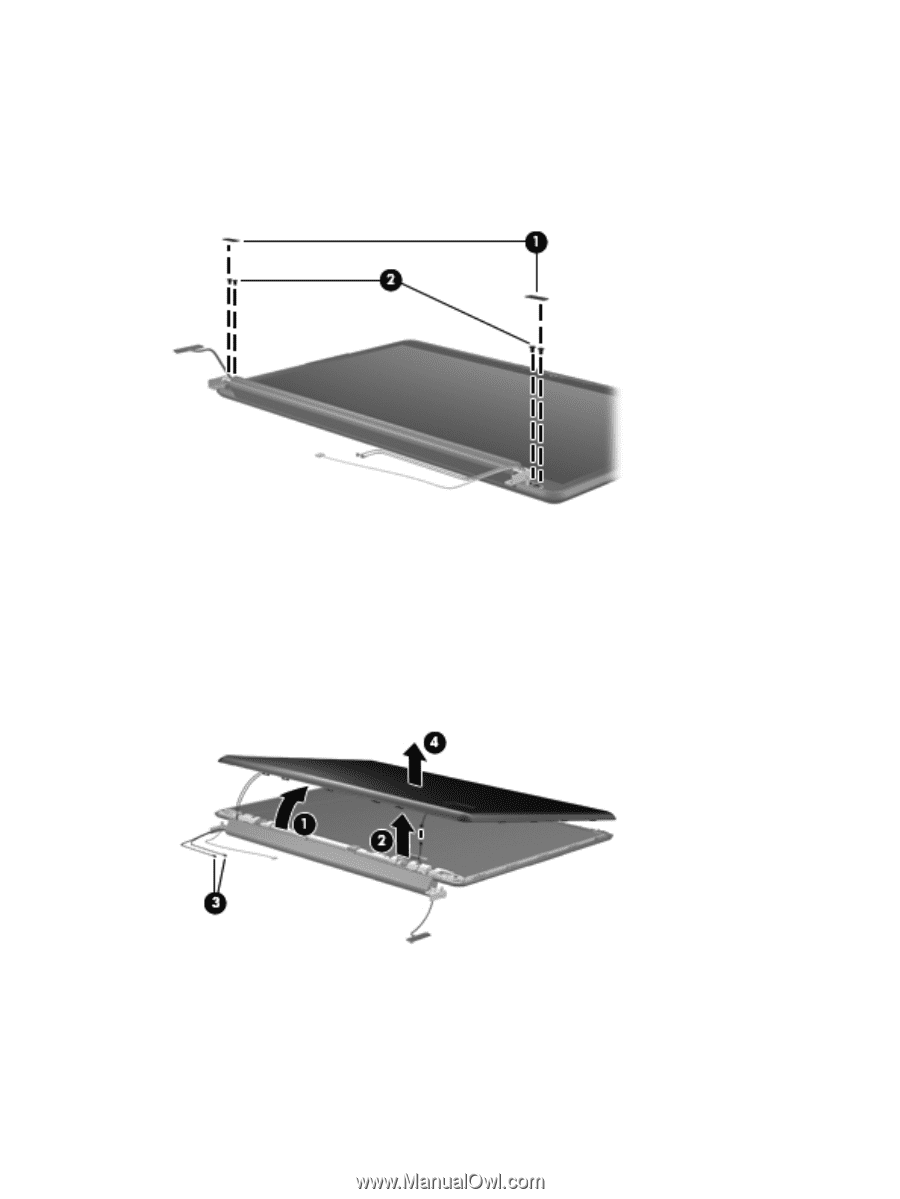
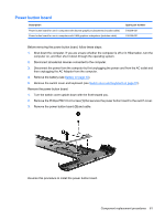
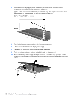
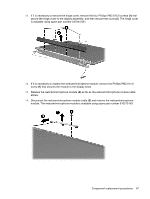
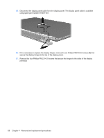
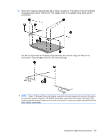
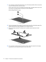
5. If it is necessary to replace the display enclosure or any of the display assembly internal components, remove the following screw covers and screws: (1) Two rubber screw covers on the display bezel bottom edge. The display rubber screw covers are included in the Display Rubber Kit, spare part number 516446-001. (2) Four Phillips PM2.5×7.0 screws. 6. Turn the display assembly upside down, with the bottom toward you. 7. Lift and release the bottom of the display enclosure (1). 8. Disconnect the display logo cable (2) from the display panel cable. 9. Route the webcam cable and antenna cables (3) through the hinge channel. 10. Remove the display enclosure (4). The display enclosure is available using spare part number 516443-001, and includes the display logo LED board and the wireless antenna transceivers and cables. 66 Chapter 4 Removal and replacement procedures
-
 1
1 -
2
-
3
-
4
-
5
-
6
-
7
-
8
-
9
-
10
-
11
-
12
-
13
-
14
-
15
-
16
-
17
-
18
-
19
-
20
-
21
-
22
-
23
-
24
-
25
-
26
-
27
-
28
-
29
-
30
-
31
-
32
-
33
-
34
-
35
-
36
-
37
-
38
-
39
-
40
-
41
-
42
-
43
-
44
-
45
-
46
-
47
-
48
-
49
-
50
-
51
-
52
-
53
-
54
-
55
-
56
-
57
-
58
-
59
-
60
-
61
-
62
-
63
-
64
-
65
-
66
-
67
-
68
-
 69
69 -
 70
70 -
 71
71 -
 72
72 -
 73
73 -
 74
74 -
 75
75 -
 76
76 -
 77
77 -
 78
78 -
 79
79 -
80
-
81
-
82
-
83
-
84
-
85
-
86
-
87
-
88
-
89
-
90
-
91
-
92
-
93
-
94
-
95
-
96
-
97
-
98
-
99
-
100
-
101
-
102
-
103
-
104
-
105
-
106
-
107
-
108
-
109
-
110
-
111
-
112
-
113
-
114
-
115
-
116
-
117
-
118
-
119
-
120
-
121
-
122
-
123
-
124
-
125
-
126
-
127
-
128
-
129
-
130
-
131
-
132
-
133
-
134
-
135
-
136
-
137
-
138
-
139
-
140
-
141
-
142
-
143
-
144
-
145
-
146
-
147
-
148
-
149
-
150
-
151
-
152
-
153
-
154
-
155
-
156
-
157
-
158
-
159
-
160
-
161
-
162
-
163
-
164
 |
 |