HP Pavilion dv7-2100 HP Pavilion dv7 Entertainment PC - Maintenance and Servic - Page 87
System board, Top cover see
 |
View all HP Pavilion dv7-2100 manuals
Add to My Manuals
Save this manual to your list of manuals |
Page 87 highlights
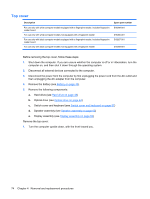
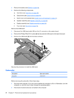
System board NOTE: The system board spare kit includes replacement thermal material. Description System board with ATI Mobility Radeon HD 4650 discrete graphics subsystem and 1-GB of dedicated memory System board with ATI Mobility Radeon HD 4650 discrete graphics subsystem and 1-GB of dedicated memory System board with ATI Mobility Radeon HD 4530 discrete graphics subsystem and 512-MB of dedicated memory System board with Intel GMA 4700MHD UMA graphics subsystem and shared memory System board bracket Spare part number 516294-001 516293-001 516292-001 516291-001 516334-001 Before removing the system board, follow these steps: 1. Shut down the computer. If you are unsure whether the computer is off or in Hibernation, turn the computer on, and then shut it down through the operating system. 2. Disconnect all external devices connected to the computer. 3. Disconnect the power from the computer by first unplugging the power cord from the AC outlet and then unplugging the AC adapter from the computer. 4. Remove the battery (see Battery on page 43). 5. Remove the following components: a. Hard drive (see Hard drive on page 48) b. Optical drive (see Optical drive on page 44) c. Switch cover (see Switch cover and keyboard on page 57) d. Speaker assembly (see Speaker assembly on page 62) e. Display assembly (see Display assembly on page 64) f. Top cover (see Top cover on page 74) When replacing the system board, be sure that the following components are removed from the defective system board and installed on the replacement system board: ● TV tuner module (see TV tuner module on page 55) ● RTC battery (see RTC battery on page 53) ● Memory module (see Memory module on page 54) ● WLAN module (see Bluetooth module on page 63) ● Modem module (see Modem module on page 77) Component replacement procedures 79
-
 1
1 -
2
-
3
-
4
-
5
-
6
-
7
-
8
-
9
-
10
-
11
-
12
-
13
-
14
-
15
-
16
-
17
-
18
-
19
-
20
-
21
-
22
-
23
-
24
-
25
-
26
-
27
-
28
-
29
-
30
-
31
-
32
-
33
-
34
-
35
-
36
-
37
-
38
-
39
-
40
-
41
-
42
-
43
-
44
-
45
-
46
-
47
-
48
-
49
-
50
-
51
-
52
-
53
-
54
-
55
-
56
-
57
-
58
-
59
-
60
-
61
-
62
-
63
-
64
-
65
-
66
-
67
-
68
-
69
-
70
-
71
-
72
-
73
-
74
-
75
-
76
-
77
-
78
-
79
-
80
-
81
-
 82
82 -
 83
83 -
 84
84 -
 85
85 -
 86
86 -
 87
87 -
 88
88 -
 89
89 -
 90
90 -
 91
91 -
 92
92 -
93
-
94
-
95
-
96
-
97
-
98
-
99
-
100
-
101
-
102
-
103
-
104
-
105
-
106
-
107
-
108
-
109
-
110
-
111
-
112
-
113
-
114
-
115
-
116
-
117
-
118
-
119
-
120
-
121
-
122
-
123
-
124
-
125
-
126
-
127
-
128
-
129
-
130
-
131
-
132
-
133
-
134
-
135
-
136
-
137
-
138
-
139
-
140
-
141
-
142
-
143
-
144
-
145
-
146
-
147
-
148
-
149
-
150
-
151
-
152
-
153
-
154
-
155
-
156
-
157
-
158
-
159
-
160
-
161
-
162
-
163
-
164
 |
 |
