HP Pavilion g6-2200 HP Pavilion g6 Notebook PC Maintenance and Service Guide - Page 57
WLAN module, Disconnect the WLAN antenna cables
 |
View all HP Pavilion g6-2200 manuals
Add to My Manuals
Save this manual to your list of manuals |
Page 57 highlights
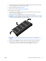
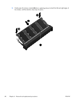
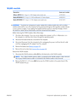
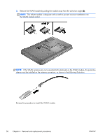
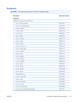
WLAN module Description Atheros HB125 802.11b/g/n 1×1 WiFi Adapter (select models only) Ralink RT3290LE 802.11 b/g/n 1x1 WiFi and Bluetooth 4.0 Combo Adapter Ralink RT5390R 802.11 b/g/n 1×1 WiFi Adapter (select models only) Spare part number 675794-001 690020-001 691415-001 CAUTION: To prevent an unresponsive system, replace the wireless module only with a wireless module authorized for use in the computer by the governmental agency that regulates wireless devices in your country or region. If you replace the module and then receive a warning message, remove the module to restore device functionality, and then contact technical support. Before removing the WLAN module, follow these steps: 1. Shut down the computer. If you are unsure whether the computer is off or in Hibernation, turn the computer on, and then shut it down through the operating system. 2. Disconnect all external devices connected to the computer. 3. Disconnect the power from the computer by first unplugging the power cord from the AC outlet and then unplugging the AC adapter from the computer. 4. Remove the battery (see Battery on page 40). 5. Remove the service door (see Service door on page 41). Remove the WLAN module: 1. Disconnect the WLAN antenna cables (1) from the terminals on the WLAN module. NOTE: The 1/black WLAN antenna cable is connected to the WLAN module 1/Main terminal. The 2/gray WLAN antenna cable is connected to the WLAN module 2/Aux terminal. 2. Remove the PM 2.5 × 2.5 screw (2) that secures the WLAN module to the system board. (The WLAN module tilts up.) ENWW Component replacement procedures 49
-
 1
1 -
2
-
3
-
4
-
5
-
6
-
7
-
8
-
9
-
10
-
11
-
12
-
13
-
14
-
15
-
16
-
17
-
18
-
19
-
20
-
21
-
22
-
23
-
24
-
25
-
26
-
27
-
28
-
29
-
30
-
31
-
32
-
33
-
34
-
35
-
36
-
37
-
38
-
39
-
40
-
41
-
42
-
43
-
44
-
45
-
46
-
47
-
48
-
49
-
50
-
51
-
 52
52 -
 53
53 -
 54
54 -
 55
55 -
 56
56 -
 57
57 -
 58
58 -
 59
59 -
 60
60 -
 61
61 -
 62
62 -
63
-
64
-
65
-
66
-
67
-
68
-
69
-
70
-
71
-
72
-
73
-
74
-
75
-
76
-
77
-
78
-
79
-
80
-
81
-
82
-
83
-
84
-
85
-
86
-
87
-
88
-
89
-
90
-
91
-
92
-
93
-
94
-
95
-
96
-
97
-
98
-
99
-
100
-
101
-
102
-
103
-
104
-
105
-
106
-
107
-
108
-
109
-
110
-
111
-
112
-
113
-
114
-
115
-
116
-
117
-
118
-
119
-
120
-
121
-
122
-
123
-
124
 |
 |
