HP Presario CQ71-100 Compaq Presario CQ71 Notebook PC and HP G71 Notebook PC - - Page 85
Remove the system board
 |
View all HP Presario CQ71-100 manuals
Add to My Manuals
Save this manual to your list of manuals |
Page 85 highlights
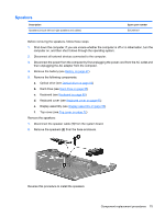
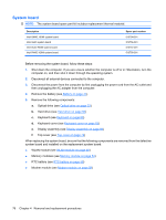
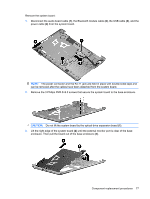
Remove the system board: 1. Disconnect the audio board cable (1), the Bluetooth module cable (2), the USB cable (3), and the power cable (4) from the system board. NOTE: The power connector and the RJ-11 jack are held in place with double-sided tape and can be removed after the cables have been detached from the system board. 2. Remove the 3 Phillips PM2.5×6.0 screws that secure the system board to the base enclosure. CAUTION: Do not lift the system board by the optical drive expansion board (1). 3. Lift the right edge of the system board (2) until the external monitor port is clear of the base enclosure. Then pull the board out of the base enclosure (3). Component replacement procedures 77
-
 1
1 -
2
-
3
-
4
-
5
-
6
-
7
-
8
-
9
-
10
-
11
-
12
-
13
-
14
-
15
-
16
-
17
-
18
-
19
-
20
-
21
-
22
-
23
-
24
-
25
-
26
-
27
-
28
-
29
-
30
-
31
-
32
-
33
-
34
-
35
-
36
-
37
-
38
-
39
-
40
-
41
-
42
-
43
-
44
-
45
-
46
-
47
-
48
-
49
-
50
-
51
-
52
-
53
-
54
-
55
-
56
-
57
-
58
-
59
-
60
-
61
-
62
-
63
-
64
-
65
-
66
-
67
-
68
-
69
-
70
-
71
-
72
-
73
-
74
-
75
-
76
-
77
-
78
-
79
-
 80
80 -
 81
81 -
 82
82 -
 83
83 -
 84
84 -
 85
85 -
 86
86 -
 87
87 -
 88
88 -
 89
89 -
 90
90 -
91
-
92
-
93
-
94
-
95
-
96
-
97
-
98
-
99
-
100
-
101
-
102
-
103
-
104
-
105
-
106
-
107
-
108
-
109
-
110
-
111
-
112
-
113
-
114
-
115
-
116
-
117
-
118
-
119
-
120
-
121
-
122
-
123
-
124
-
125
-
126
-
127
-
128
-
129
-
130
-
131
-
132
-
133
-
134
-
135
-
136
-
137
-
138
-
139
-
140
-
141
-
142
-
143
-
144
 |
 |
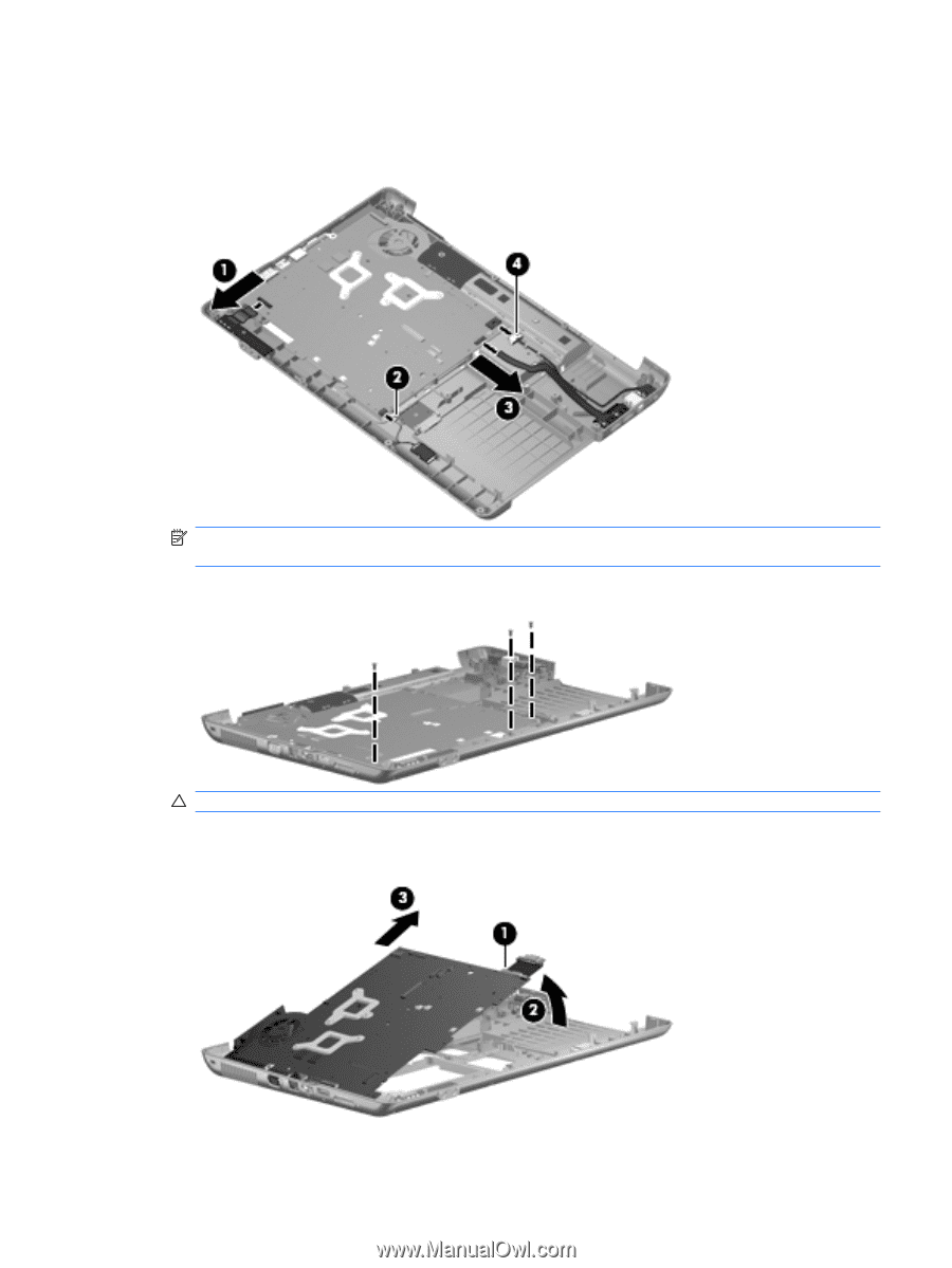
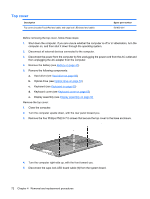
Remove the system board:
1.
Disconnect the audio board cable
(1)
, the Bluetooth module cable
(2)
, the USB cable
(3)
, and the
power cable
(4)
from the system board.
NOTE:
The power connector and the RJ-11 jack are held in place with double-sided tape and
can be removed after the cables have been detached from the system board.
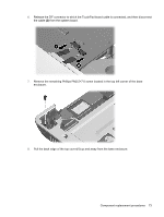
2.
Remove the 3 Phillips PM2.5×6.0 screws that secure the system board to the base enclosure.
CAUTION:
Do not lift the system board by the optical drive expansion board
(1)
.
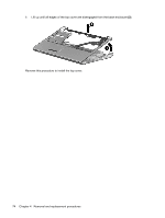
3.
Lift the right edge of the system board
(2)
until the external monitor port is clear of the base
enclosure. Then pull the board out of the base enclosure
(3)
.
Component replacement procedures
77