HP ProBook 655 Maintenance and Service Guide - Page 85
Fan/heat sink assembly see
 |
View all HP ProBook 655 manuals
Add to My Manuals
Save this manual to your list of manuals |
Page 85 highlights
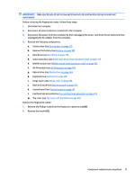
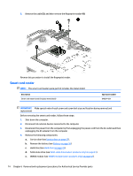
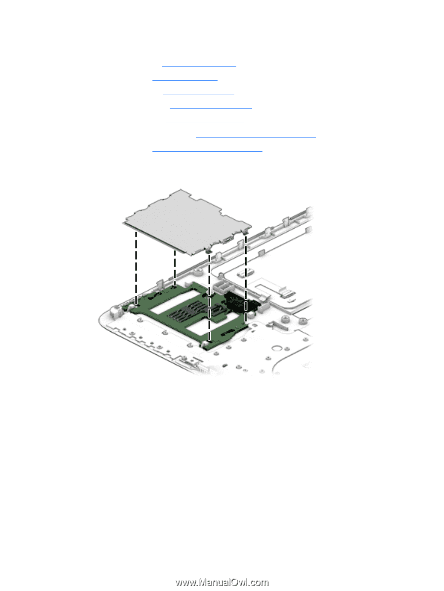
f. WLAN module (see WLAN module on page 44). g. Optical drive (see Optical drive on page 46). h. Keyboard (see Keyboard on page 48). i. Hinge covers (see Hinge cover on page 55). j. Base enclosure (see Base enclosure on page 57). k. System board (see System board on page 59). l. Fan/heat sink assembly (see Fan and heat sink assembly on page 61). m. Top cover (see Top cover and TouchPad on page 65). Remove the smart card reader: ▲ Remove the metal shield, and then lift the smart card reader to remove it. Reverse this procedure to install the smart card reader. Component replacement procedures 75
-
 1
1 -
2
-
3
-
4
-
5
-
6
-
7
-
8
-
9
-
10
-
11
-
12
-
13
-
14
-
15
-
16
-
17
-
18
-
19
-
20
-
21
-
22
-
23
-
24
-
25
-
26
-
27
-
28
-
29
-
30
-
31
-
32
-
33
-
34
-
35
-
36
-
37
-
38
-
39
-
40
-
41
-
42
-
43
-
44
-
45
-
46
-
47
-
48
-
49
-
50
-
51
-
52
-
53
-
54
-
55
-
56
-
57
-
58
-
59
-
60
-
61
-
62
-
63
-
64
-
65
-
66
-
67
-
68
-
69
-
70
-
71
-
72
-
73
-
74
-
75
-
76
-
77
-
78
-
79
-
 80
80 -
 81
81 -
 82
82 -
 83
83 -
 84
84 -
 85
85 -
 86
86 -
 87
87 -
 88
88 -
 89
89 -
 90
90 -
91
-
92
-
93
-
94
-
95
-
96
-
97
-
98
-
99
-
100
-
101
-
102
-
103
-
104
-
105
-
106
-
107
-
108
-
109
-
110
-
111
-
112
-
113
-
114
-
115
-
116
-
117
-
118
-
119
-
120
-
121
-
122
-
123
-
124
-
125
-
126
-
127
-
128
-
129
-
130
-
131
-
132
-
133
-
134
-
135
-
136
-
137
-
138
-
139
-
140
-
141
-
142
-
143
-
144
-
145
-
146
 |
 |
f.
WLAN module (see
WLAN module
on page
44
).
g.
Optical drive (see
Optical drive
on page
46
).
h.
Keyboard (see
Keyboard
on page
48
).
i.
Hinge covers (see
Hinge cover
on page
55
).
j.
Base enclosure (see
Base enclosure
on page
57
).
k.
System board (see
System board
on page
59
).
l.
Fan/heat sink assembly (see
Fan and heat sink assembly
on page
61
).
m.
Top cover (see
Top cover and TouchPad
on page
65
).
Remove the smart card reader:
▲
Remove the metal shield, and then lift the smart card reader to remove it.
Reverse this procedure to install the smart card reader.
Component replacement procedures
75