HP ProLiant BL660c HP BladeSystem Networking Reference Architecture: HP Virtua - Page 3
Virtual Connect FlexFabric Module Hardware Overview
 |
View all HP ProLiant BL660c manuals
Add to My Manuals
Save this manual to your list of manuals |
Page 3 highlights
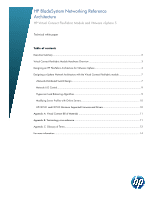
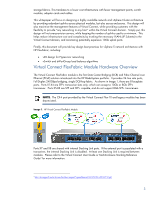
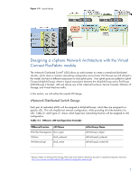
storage fabrics. This translates to a lower cost infrastructure with fewer management points, switch modules, adapter cards and cables. This whitepaper will focus on designing a highly available network and vSphere Cluster architecture by providing redundant uplinks across physical modules, but also across enclosures. This design will also maximize the management features of Virtual Connect, while providing customers with the flexibility to provide "any networking to any host" within the Virtual Connect domain. Simply put, this design will not over-provision servers, while keeping the number of uplinks used to a minimum. This helps reduce infrastructure cost and complexity by trunking the necessary VLANs (IP Subnets) to the Virtual Connect domain, and minimizing potentially expensive 10Gb uplink ports. Finally, this document will provide key design best practices for vSphere 5 network architecture with HP FlexFabric, including: vDS design for Hypervisor networking vSwitch and dvPortGroup load balance algorithms Virtual Connect FlexFabric Module Hardware Overview The Virtual Connect FlexFabric module is the first Data Center Bridging (DCB) and Fibre Channel over Ethernet (FCoE) solution introduced into the HP BladeSystem portfolio. It provides 24 line rate ports, Full-Duplex 240Gbps bridging, single DCB-hop fabric. As shown in Image 1, there are 8 faceplate ports. Ports X1-X4 are SFP+ transceiver slots only; which can accept a 10Gb or 8Gb SFP+ transceiver. Ports X5-X8 are SFP and SFP+ capable, and do not support 8Gb SFP+ transceivers. NOTE: The CX-4 port provided by the Virtual Connect Flex-10 and legacy modules has been depreciated. Image 1: HP Virtual Connect FlexFabric Module Ports X7 and X8 are shared with internal Stacking Link ports. If the external port is populated with a transceiver, the internal Stacking Link is disabled. At least one Stacking Link is required between modules. Please refer to the Virtual Connect User Guide or Multi-Enclosure Stacking Reference Guide3 for more information. 3 http://bizsupport2.austin.hp.com/bc/docs/support/SupportManual/c02102153/c02102153.pdf 3
-
 1
1 -
 2
2 -
 3
3 -
 4
4 -
 5
5 -
 6
6 -
 7
7 -
 8
8 -
 9
9 -
10
-
11
-
12
-
13
-
14
 |
 |