HP ProLiant SL170s HP ProLiant SL170s G6 Server Maintenance and Service Guide
HP ProLiant SL170s - G6 Server Manual
 |
View all HP ProLiant SL170s manuals
Add to My Manuals
Save this manual to your list of manuals |
HP ProLiant SL170s manual content summary:
- HP ProLiant SL170s | HP ProLiant SL170s G6 Server Maintenance and Service Guide - Page 1
HP ProLiant SL170s G6 Server Maintenance and Service Guide Part number 625207-001 October 2010 First edition - HP ProLiant SL170s | HP ProLiant SL170s G6 Server Maintenance and Service Guide - Page 2
to change without notice. The only warranties for HP products and services are set forth in the express warranty statements accompanying such products and services. Nothing herein should be construed as constituting an additional warranty. HP shall not be liable for technical or editorial errors - HP ProLiant SL170s | HP ProLiant SL170s G6 Server Maintenance and Service Guide - Page 3
instructions...27 Server Warnings and Cautions ...27 Symbols on Equipment ...28 Powering Down the Server...29 System tray Removal and Replacement Procedures 29 Drives and personality board ...31 Cable Management ...31 Cable Connections...32 Hard Drives...33 Personality board ...35 System Board - HP ProLiant SL170s | HP ProLiant SL170s G6 Server Maintenance and Service Guide - Page 4
Setup Utility Menu Bar ...64 BIOS Update ...69 Clear CMOS ...70 Power-on Self-Test (POST)...70 POST Error Indicators ...71 POST Errors Message Definition ...71 POST Related Troubleshooting...76 Physical and Operating Specifications 78 System Unit ...78 Index ...81 Customer self repair 4 - HP ProLiant SL170s | HP ProLiant SL170s G6 Server Maintenance and Service Guide - Page 5
period HP (or HP service providers or service partners) identifies that the repair can be accomplished by the use of a CSR part, HP will ship is required, you can call the HP Technical Support Center and a technician will help you over the telephone. HP specifies in the materials shipped with a - HP ProLiant SL170s | HP ProLiant SL170s G6 Server Maintenance and Service Guide - Page 6
pièce défectueuse, HP se réserve le droit de vous facturer les coûts de remplacement. Dans le cas d'une pièce CSR, HP supporte l'ensemble des frais le site Web HP (http://www.hp.com/go/selfrepair). Service de garantie "pièces seules" Votre garantie limitée HP peut inclure un service de garantie "pi - HP ProLiant SL170s | HP ProLiant SL170s G6 Server Maintenance and Service Guide - Page 7
due categorie di parti CSR: • Obbligatorie - Parti che devono essere necessariamente riparate dal cliente. Se il cliente ne affida la riparazione ad HP, deve sostenere le spese di spedizione e di manodopera per il servizio. • Opzionali - Parti la cui riparazione da parte del cliente è facoltativa - HP ProLiant SL170s | HP ProLiant SL170s G6 Server Maintenance and Service Guide - Page 8
Sie jedoch den Austausch dieser Teile von HP vornehmen lassen möchten, können bei diesem Service je nach den für Ihr Produkt vorgesehenen verfügbar. Wenn Sie Hilfe benötigen, können Sie das HP technische Support Center anrufen und sich von einem Mitarbeiter per Telefon helfen lassen. Den - HP ProLiant SL170s | HP ProLiant SL170s G6 Server Maintenance and Service Guide - Page 9
componentes CSR se clasifican en dos categorías: • Obligatorio: componentes para los que la reparación por parte del usuario es obligatoria. Si solicita a HP que realice la sustitución de estos componentes, tendrá que hacerse cargo de los gastos de desplazamiento y de mano de obra de dicho servicio - HP ProLiant SL170s | HP ProLiant SL170s G6 Server Maintenance and Service Guide - Page 10
minimum beperkt kan blijven en de flexibiliteit in het vervangen van defecte onderdelen groter is. Deze onderdelen worden CSR-onderdelen (Customer Self Repair) genoemd. Als HP (of een HP Service Partner) bij de diagnose vaststelt dat de reparatie kan worden uitgevoerd met een CSRonderdeel, verzendt - HP ProLiant SL170s | HP ProLiant SL170s G6 Server Maintenance and Service Guide - Page 11
diretamente ao cliente. Existem duas categorias de peças CSR: • Obrigatória - Peças cujo reparo feito pelo cliente é obrigatório. Se desejar que a HP substitua essas peças, serão cobradas as despesas de transporte e mão-de-obra do serviço. • Opcional - Peças cujo reparo feito pelo cliente é opcional - HP ProLiant SL170s | HP ProLiant SL170s G6 Server Maintenance and Service Guide - Page 12
Customer self repair 12 - HP ProLiant SL170s | HP ProLiant SL170s G6 Server Maintenance and Service Guide - Page 13
Customer self repair 13 - HP ProLiant SL170s | HP ProLiant SL170s G6 Server Maintenance and Service Guide - Page 14
Customer self repair 14 - HP ProLiant SL170s | HP ProLiant SL170s G6 Server Maintenance and Service Guide - Page 15
Customer self repair 15 - HP ProLiant SL170s | HP ProLiant SL170s G6 Server Maintenance and Service Guide - Page 16
2 s6500 Chassis 4U None 3 SL170s right tray None 4 Top cover of power supply None 1Mandatory-Parts for which customer self repair is mandatory. If you request HP to replace these parts, you will be charged for the travel and labor costs of this service. 2Optional-Parts for which customer - HP ProLiant SL170s | HP ProLiant SL170s G6 Server Maintenance and Service Guide - Page 17
optional ist. Diese Teile sind auch für Customer Self Repair ausgelegt. Wenn Sie jedoch den Austausch dieser Teile von HP vornehmen lassen möchten, können bei diesem Service je nach den für Ihr Produkt vorgesehenen Garantiebedingungen zusätzliche Kosten anfallen. 3No: Kein-Einige Teile sind nicht - HP ProLiant SL170s | HP ProLiant SL170s G6 Server Maintenance and Service Guide - Page 18
met de garantievoorwaarden moet het onderdeel door een geautoriseerde Service Partner worden vervangen. Deze onderdelen worden in de ém são projetadas para o reparo feito pelo cliente. No entanto, se desejar que a HP as substitua, pode haver ou não a cobrança de taxa adicional, dependendo do tipo - HP ProLiant SL170s | HP ProLiant SL170s G6 Server Maintenance and Service Guide - Page 19
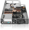
components Item Description 1 System Board 2 Front PCIE 3 X16 PCIe Riser Card w/Modkey X16 PCIe Riser Card 4 Thermal Sensor Board 5 IPMI Riser Board 6 Hard Drive Options Hard Drive, SAS 300GB 15K 6G LFF Hard Drive, SAS 300GB 10K 6G 2.5 Hard Drive, SAS 450GB 15K 3G LFF Hard Drive - HP ProLiant SL170s | HP ProLiant SL170s G6 Server Maintenance and Service Guide - Page 20
PC3-10600E 2GB DIMM PC3-10600R 2GB DIMM PC3-10600R 4GB DIMM PC3L-1600R 4GB DIMM PC3-8500R 4GB DIMM PC3-8500R 8GB 8 Processors ,Optional Series Processor Intel X5670 2.93 Ghz 12M 95W Processor Intel X5660 2.8 Ghz 12M 95W Processor Intel X5550 2.66 Ghz 12M 95W Processor Intel X5667 3.06 Ghz - HP ProLiant SL170s | HP ProLiant SL170s G6 Server Maintenance and Service Guide - Page 21
Right Cable 629821-001 Optional2 17 System Board Power 14x12P Right Cable 630655-001 SL170 Cable Kit 576897-001 Optional2 1Mandatory-Parts for which customer self repair is mandatory. If you request HP to replace these parts, you will be charged for the travel and labor costs of this service - HP ProLiant SL170s | HP ProLiant SL170s G6 Server Maintenance and Service Guide - Page 22
optional ist. Diese Teile sind auch für Customer Self Repair ausgelegt. Wenn Sie jedoch den Austausch dieser Teile von HP vornehmen lassen möchten, können bei diesem Service je nach den für Ihr Produkt vorgesehenen Garantiebedingungen zusätzliche Kosten anfallen. 3No: Kein-Einige Teile sind nicht - HP ProLiant SL170s | HP ProLiant SL170s G6 Server Maintenance and Service Guide - Page 23
ser reparados por el usuario. Para que el usuario haga valer su garantía, HP pone como condición que un proveedor de servicios autorizado realice la sustitución de met de garantievoorwaarden moet het onderdeel door een geautoriseerde Service Partner worden vervangen. Deze onderdelen worden in de ge - HP ProLiant SL170s | HP ProLiant SL170s G6 Server Maintenance and Service Guide - Page 24
Illustrated parts catalog 24 - HP ProLiant SL170s | HP ProLiant SL170s G6 Server Maintenance and Service Guide - Page 25
information available before you call HP: • Technical support registration number (if applicable) • Product serial number • Product model name and number • Applicable error messages • Add-on boards or hardware • Third-party hardware or software • Operating system type and revision level Illustrated - HP ProLiant SL170s | HP ProLiant SL170s G6 Server Maintenance and Service Guide - Page 26
compatible with the server. When you integrate new components into the system, record its model and serial are used in substep items, the alphabetically labeled instructions correspond to the numbered labels on the related tools may also be used: • HP ProLiant SL170s G6 Server Easy Set-up CD • IPMI - HP ProLiant SL170s | HP ProLiant SL170s G6 Server Maintenance and Service Guide - Page 27
. 5. Connect all external cables to the system. 6. Press the power button on the front panel to turn on the server. NOTE: The HP ProLiant SL170s G6 Server supports up to four 750-W or 1200-W power supply units. Server Warnings and Cautions Before installing a server, be sure that you understand the - HP ProLiant SL170s | HP ProLiant SL170s G6 Server Maintenance and Service Guide - Page 28
the server in this manner results in improper airflow and improper cooling that can lead to thermal damage. CAUTION: The following rack-mount instructions shall of hazardous energy circuits or electric shock hazards. Refer all servicing to qualified personnel. To reduce the risk of injury from - HP ProLiant SL170s | HP ProLiant SL170s G6 Server Maintenance and Service Guide - Page 29
and safety requirements and guidelines for manual material handling. These symbols, on power supplies or systems, indicate that the equipment is all power cords to completely disconnect power from the system. Powering Down the Server The server does not completely power down when the power button - HP ProLiant SL170s | HP ProLiant SL170s G6 Server Maintenance and Service Guide - Page 30
Figure 1 Removing the left server Figure 2 Removing the right server To replace the system tray: 1. Insert the system tray into the chassis. Removal and Replacement Procedures 30 - HP ProLiant SL170s | HP ProLiant SL170s G6 Server Maintenance and Service Guide - Page 31
Figure 3 Installing the left server Figure 4 Installing the right server Drives and personality board The server supports 2 drive bays for 3.5-inch hard disk drives or 4 drive bays for 2.5-inch hard disk drives. Cable Management Always follow good cable management practices when working - HP ProLiant SL170s | HP ProLiant SL170s G6 Server Maintenance and Service Guide - Page 32
crease a SATA data cable. • Do not rely on components like the drive cage, power supply, or system cover to push cables down into the chassis. Removing power supply cables from the system board connectors (J36) follow below steps: 1. Squeeze on the top of the retaining latch attached to the cable - HP ProLiant SL170s | HP ProLiant SL170s G6 Server Maintenance and Service Guide - Page 33
To J3 on Personality board J3 on Personality board Hard Drives One SL170s G6 server tray can accommodate up to 2 LFF or 4 SFF hard disk drives, one chassis can accommodate 8 server trays (4 left trays and 4 right trays) for up to 16 LFF or 32 SFF hard disk drives. The server supports both SAS and - HP ProLiant SL170s | HP ProLiant SL170s G6 Server Maintenance and Service Guide - Page 34
Hard Drive 4) SFF Hard Drive 4 NOTE: The following section introduces the LFF hard disk drive installation and removal. Refer to HP SFF Enablement Kit Installation Instructions for more details on SFF hard disk drive installtion. To remove LFF hard drive: 1. Slide the HDD carrier latches to unlock - HP ProLiant SL170s | HP ProLiant SL170s G6 Server Maintenance and Service Guide - Page 35
the hard drive blank. If the drive is removed in the future, you must reinstall the hard drive blank to maintain proper system airflow. Personality board To remove the Personality board: 1. Unfasten the screws that secure the Personality board to chassis. Removal and Replacement Procedures 35 - HP ProLiant SL170s | HP ProLiant SL170s G6 Server Maintenance and Service Guide - Page 36
Fasten the screws. Figure 11 Installing the personality board System Board Configuration Processor HP ProLiant SL170s G6 Server, with 8 Nodes, supports sixteen -processor operation. With two processors installed, each Node supports boot functions through the processor installed in processor socket - HP ProLiant SL170s | HP ProLiant SL170s G6 Server Maintenance and Service Guide - Page 37
supports Six-Core Intel® Westmere® EP Series processors. CAUTION: It is recommended to use processors of the same speeds or cache sizes to prevent possible server -Ib is set for the system. 1. Loosen the two mounting pins. 2. Lift the heat sink away from the system board. CAUTION: Place the heat sink - HP ProLiant SL170s | HP ProLiant SL170s G6 Server Maintenance and Service Guide - Page 38
Figure 13 Removing the heat sink assembly IMPORTANT: If the heat sink has been removed for any reason on a previously installed processor, it is critical that you apply more thermal interface material to the integrated heat spreader on the processor to ensure proper thermal bonding between the - HP ProLiant SL170s | HP ProLiant SL170s G6 Server Maintenance and Service Guide - Page 39
process install tool to insert the processor into the socket. The processor and system board spare part kits contain the processor install tool and instructions on how to use the tool. It is important to follow the instructions to prevent damage to the pins in the processor socket. To install the - HP ProLiant SL170s | HP ProLiant SL170s G6 Server Maintenance and Service Guide - Page 40
Figure 17 Installing the processor 4. Press down firmly until the processor installation tool clicks and separates from the processor, and then remove the processor installation tool. Figure 18 Removing the processor installation tool 5. Close the processor socket retaining bracket and the processor - HP ProLiant SL170s | HP ProLiant SL170s G6 Server Maintenance and Service Guide - Page 41
Wipe the contact surfaces several times to make sure that no particles or dust contaminants are evident. CAUTION: HP recommends using Shin-Etsu X-23-7783D thermal grease compound for your ProLiant server. 2. Apply all the grease to the top of the processor in one of the following patterns to insure - HP ProLiant SL170s | HP ProLiant SL170s G6 Server Maintenance and Service Guide - Page 42
over the processor pins or the system board base, which can cause electrical shorts that damage the system. To install the heat sink: CAUTION: To prevent overheating or a possible system crash, use only a heat sink model specified for the HP ProLiant SL170s G6 Server. 1. Put the heat sink frame on - HP ProLiant SL170s | HP ProLiant SL170s G6 Server Maintenance and Service Guide - Page 43
Figure 22 Population Order of DIMM Sockets To remove memory module: 1. Completely open the holding clips securing the module. 2. Gently pull the memory module upward to remove it from the slot. Figure 23 Removing a memory module CAUTION: Place the memory module on a static-dissipating work surface - HP ProLiant SL170s | HP ProLiant SL170s G6 Server Maintenance and Service Guide - Page 44
not close, the module is not inserted correctly. NOTE: The ProLiant SL170s G6 Server supports up to 128-memory-modules. Install them in the DIMM slots starting from the DIMM 1 slot. IPMI Card To remove the IPMI optional card from the system board 1 Loosen the screws that secure the IPMI card to the - HP ProLiant SL170s | HP ProLiant SL170s G6 Server Maintenance and Service Guide - Page 45
the IPMI card straight down into the expansion connector on the system board. 3. Fasten the screws back to secure the system board and IPMI card to the tray. Figure 26 Installing the IPMI card to the system board System Battery The server uses nonvolatile memory that requires 1 battery to retain - HP ProLiant SL170s | HP ProLiant SL170s G6 Server Maintenance and Service Guide - Page 46
the system battery: • Replace the battery with the same type as the battery recommended by HP. Use of used batteries according to manufacturer's instructions. CAUTION: Loss of BIOS settings occurs server no longer automatically displays the correct date and time, you may need to replace the system - HP ProLiant SL170s | HP ProLiant SL170s G6 Server Maintenance and Service Guide - Page 47
of these parts. 1. Remove the six screws that secure the system board to the tray. 2. Release the system board from the tray. Figure 29 Removing the system board from the tray IMPORTANT: Do not discard the screws. If the system board is removed in the future, you must keep them for future - HP ProLiant SL170s | HP ProLiant SL170s G6 Server Maintenance and Service Guide - Page 48
board. Refer to the "Navigating through the Setup Utility" section on page 61 to input the correct System Serial Number and Asset Tag information. Also, you can input all the other customer specific setup requirements that are required. Power Supply Unit (PSU) Located on the rear panel of the server - HP ProLiant SL170s | HP ProLiant SL170s G6 Server Maintenance and Service Guide - Page 49
shock hazards and/or damage to the equipment. • Installation of power supply units should be referred to individuals who are qualified to service server systems and are trained to deal with equipment capable of generating hazardous energy levels. • DO NOT open the power supply unit. There are no - HP ProLiant SL170s | HP ProLiant SL170s G6 Server Maintenance and Service Guide - Page 50
Figure 32 Removing the PSU Backplane vb To remove the power supply: 1. Press the port colored button on the power supply latch. 2. Slide the power supply out of the power supply bay. Figure 33 Removing the Power supply To replace the PSU Backplane: 1. Remove the top cover from the power supply cage - HP ProLiant SL170s | HP ProLiant SL170s G6 Server Maintenance and Service Guide - Page 51
supply into the power supply bay until it snaps into place. Figure 35 Installing the power supply System Fan The server has eight system fans located on the rear panel of chassis. The server supports Redundant Fan. NOTE: CAN NOT mix Redundant Fan with none-Redundant Fan in the same chassis. The - HP ProLiant SL170s | HP ProLiant SL170s G6 Server Maintenance and Service Guide - Page 52
2 3 Fan 3 4 Fan 4 5 Fan 5 6 Fan 6 7 Fan 7 8 Fan 8 A new system fan can be installed to allow the server to operate properly in case a default system fan becomes defective. To remove the system fan: 1. Squeeze the two release tabs on the system fan together to release it from the chassis - HP ProLiant SL170s | HP ProLiant SL170s G6 Server Maintenance and Service Guide - Page 53
Figure 37 Removing the system fan To replace the system fan: 1. Insert the system fan into the chassis. Figure 38 Installing the system fan Removal and Replacement Procedures 53 - HP ProLiant SL170s | HP ProLiant SL170s G6 Server Maintenance and Service Guide - Page 54
buttons, and LED indicators located on the front panel, rear panel of the HP ProLiant SL170s G6 Server. Connectors and Components Front Panel Components Figure 39 Front panel components of SL170s G6 server system Item 1 2 3 4 5 6 7 8 9 Description VGA port Serial port Health LED/SW Top: 1GbE NIC2 - HP ProLiant SL170s | HP ProLiant SL170s G6 Server Maintenance and Service Guide - Page 55
Rear panel components Figure 40 Rear panel components of SL170s G6 server system Item 1 2 3 4 5 6 Description Power Supply 1 Power Supply 2 Power Supply 3 Power Supply 4 UID LED/SW APM Connector Connectors, Switches, and LEDs 55 - HP ProLiant SL170s | HP ProLiant SL170s G6 Server Maintenance and Service Guide - Page 56
System board components Figure 41 System board components Item 1 2 3 4 5 6 7 8 9 10 11 12 Designator Description J44 VGA Port CN1 Serial port SW4 UID LED/SW CR6 Health LED SW3 Power LED/SW J41 - HP ProLiant SL170s | HP ProLiant SL170s G6 Server Maintenance and Service Guide - Page 57
take appropriate measures to ensure the integrity of the system data. If you suspect a TPM board failure, leave the TPM installed and remove the system board. Contact an HP authorized service provider for a replacement system board and TPM board. Jumpers -Password and Chassis ID Password (J50) and - HP ProLiant SL170s | HP ProLiant SL170s G6 Server Maintenance and Service Guide - Page 58
and external status LED indicators located on the: • Front panel • Rear panel These LED indicators aid in problem diagnosis by indicating the status of system components and operations of the server. Front panel LED indicators The front panel LED indicators allow constant monitoring of basic - HP ProLiant SL170s | HP ProLiant SL170s G6 Server Maintenance and Service Guide - Page 59
Table 7 UID LED indicator status Components UID LED indicator Status Blue Blue(Blinking) Off Descriptions Identification System is being remotely managed Off Power LED Indicator The power status of the server is indicated by the bicolor LED on the front panel. Connectors, Switches, and LEDs 59 - HP ProLiant SL170s | HP ProLiant SL170s G6 Server Maintenance and Service Guide - Page 60
LED indicator status Component Status Description Power LED indicator Steady green Steady Amber Off The server is operating normally. The server is system off or in hibernation with A/C power. The server is system off without A/C power. Rear panel LED indicators This LED can be toggled by - HP ProLiant SL170s | HP ProLiant SL170s G6 Server Maintenance and Service Guide - Page 61
Figure 45 UID/LED indicator location Table 9 UID/LED indicator states Item Component UID LED indicator Status Blue Blue(Blinking) Off Description Identification System is being remotely managed Off Connectors, Switches, and LEDs 61 - HP ProLiant SL170s | HP ProLiant SL170s G6 Server Maintenance and Service Guide - Page 62
server platforms. This software contains a set of programs permanently stored in an EEPROM chipset located on the system board. on the monitor and server. 2. If the server is already turned on, save your data and exit all open applications, then restart the server. 3. When the HP logo is displayed - HP ProLiant SL170s | HP ProLiant SL170s G6 Server Maintenance and Service Guide - Page 63
display highlight. Moves the cursor to the first/last item (each menu), the item will be display highlight. To load Failsafe Defaults To load default system values. To save changes and close the Setup Utility. Diagnostic tools and Setup Utilities 63 - HP ProLiant SL170s | HP ProLiant SL170s G6 Server Maintenance and Service Guide - Page 64
. The menu bar choices are described in the topics below. For more details, please refer to HP ProLiant Software Configuration Guide. Main Menu Figure 47 Main menu of BIOS setup utility 1 Use this menu to set the system time and date, and configure of the following items: • View BIOS build date and - HP ProLiant SL170s | HP ProLiant SL170s G6 Server Maintenance and Service Guide - Page 65
• View CPU type / CPU speed /CPU physical count information. • View System memory size. • View System serial number. • View MAC address for the embedded NIC. • Set Server Asset Tag. • Set system time and date. • Set boot features: ○ Enable or Disable POST Speed up. ○ Enable or Disable Splash screen. - HP ProLiant SL170s | HP ProLiant SL170s G6 Server Maintenance and Service Guide - Page 66
Figure 49 IPMI configuration menu of the BIOS setup utility • SEL Configuration - Configuration of the BMC System Event Log. • Serial Port Configuration - Select to configure system serial ports. • LAN Configuration - Select for LAN configuration. • Watchdog Configuration - Select to configure POST - HP ProLiant SL170s | HP ProLiant SL170s G6 Server Maintenance and Service Guide - Page 67
the BIOS setup utility Use this menu to configure the boot settings. • Boot Device Priority - Use this screen to specify the order in which the system checks for a boot device. • USB Device Boot Priority - Use this screen to control the latest added USB Functions by setting the item to the desired - HP ProLiant SL170s | HP ProLiant SL170s G6 Server Maintenance and Service Guide - Page 68
Admin Password --- Allows you to access and change all settings in the Setup Utility. The administrator password allows you to configure access for system users. To set a new administrator password: 1. In the Security screen, select a set password field - Change Admin Password, and then press Enter - HP ProLiant SL170s | HP ProLiant SL170s G6 Server Maintenance and Service Guide - Page 69
(A-Z, a-z, 0-9) are recommended to avoid system error. 4 Retype the password to or discard changes. When you save and exit, the server reboots. • Save Changes and Exit --- Save the changes and followed with direction to complete the steps. "ProLiant Flash Update" interface will appear. 3. Select - HP ProLiant SL170s | HP ProLiant SL170s G6 Server Maintenance and Service Guide - Page 70
○ Create a label for the ROMPaq diskette ○ Network ROM Flashing Capabilities 4. Reboot SL170s G6 Server with one of the above bootable devices and make sure the BIOS setting allows booting from the USB disk. 5. Follow the on-screen instructions to finish the flashing of the BIOS. Clear CMOS You may - HP ProLiant SL170s | HP ProLiant SL170s G6 Server Maintenance and Service Guide - Page 71
error messages with corresponding troubleshooting recommendation. HP recommends that you correct the error, even if the server appears to boot successfully the 8254 timer. This may indicate a problem with system hardware. Requires repair of the system board. CMOS Battery is low. This message usually - HP ProLiant SL170s | HP ProLiant SL170s G6 Server Maintenance and Service Guide - Page 72
password. Keyboard/Interface Error Keyboard controller failed test. This may indicate a problem with system hardware. S.M.A.R.T. Status BAD, Backup and Hard Disk S.M.A.R.T feature test fail Replace ,indicate a problem with hard disk Password check failed If user input incorrect password more - HP ProLiant SL170s | HP ProLiant SL170s G6 Server Maintenance and Service Guide - Page 73
installed, this will appear and system will halt. BMC Recovery Jumper Set or BMC Firmware corrupted! When install the Jumper J53 or BMC firmware corrupt, this will appear. When unistall Inlet Ambient sensor Inlet Ambient Sensor Cable Did Not board or the sensor board cable get Get Plugged or - HP ProLiant SL170s | HP ProLiant SL170s G6 Server Maintenance and Service Guide - Page 74
and the other fans will run at high speed. If two fans missing, this will appear and system will shutdown in minutes. If system fan2b is not installed or failed, when one fan missing, system will announce this message and other fans will run at high speed. When two fans missing at the - HP ProLiant SL170s | HP ProLiant SL170s G6 Server Maintenance and Service Guide - Page 75
and the other fans will run at high speed. If two fans missing, this will appear and system will shutdown in minutes. If system fan4b is not installed or failed, when one fan missing, system will announce this message and other fans will run at high speed. When two fans missing at the - HP ProLiant SL170s | HP ProLiant SL170s G6 Server Maintenance and Service Guide - Page 76
and other fans will run at high speed. When two fans missing at the same time, this will appear and system will shutdown in minutes. POST Related Troubleshooting Perform the following procedures when POST fails to run, displays error messages, or emits beep codes. Diagnostic tools and Setup - HP ProLiant SL170s | HP ProLiant SL170s G6 Server Maintenance and Service Guide - Page 77
firmly plugged in. • The power outlet to the server should be connected and works correctly. • The server and monitor are both turned on. The bicolour status are properly connected and all boards firmly seated. • The processor is fully seated in its socket on the system board. • The cooler assembly - HP ProLiant SL170s | HP ProLiant SL170s G6 Server Maintenance and Service Guide - Page 78
HP ProLiant SL170s G6 Server. Specifications include: System Unit Table 12 Hardware Specifications Item Processor socket Processor support connector on the system board), video port, serial port and two GbE port • Power/system health status • UID status Rear Panel System Board • LAN activity - HP ProLiant SL170s | HP ProLiant SL170s G6 Server Maintenance and Service Guide - Page 79
Components 1200W Redundant, power supply 750W Redundant, power supply Eight 80mm system fans Table 13 Physical Dimensions Item System board platform System board dimension Dimensions (H x W x D) (with bezel) Server weight (approximate) Description ATX (Advanced Technology Extended) 17.935''x6 - HP ProLiant SL170s | HP ProLiant SL170s G6 Server Maintenance and Service Guide - Page 80
ratings use the Power Calculator which is available via the online tool located at URL: http://h18000.www1.hp.com/products/solutions/power/advisor-online/HPPowerAdvisor.html -Click on the system of interest. -Follow the instructions of the next screens. Physical and Operating Specifications 80 - HP ProLiant SL170s | HP ProLiant SL170s G6 Server Maintenance and Service Guide - Page 81
, 62 BIOS software, 62 BIOS update, 69 clear CMOS, 70 POST, 70 dimensions server, 79 Drives and Personality board cable management, 31 hard drives, 33 Personality board, 35 Drives, Front I/O and Personality board cable connections, 32 E electric shock symbol, 28 warning, 27 F front panel components - HP ProLiant SL170s | HP ProLiant SL170s G6 Server Maintenance and Service Guide - Page 82
, 36 physical dimensions system board, 79 Power LED indicator, 59 Power supply spare part number, 21 power supply unit. See PSU Power/data Backplane Board spare part number, 21 power-down procedures, 29 Power-On Self Test POST error indicators, 70 POST related troubleshooting, 76 recoverable POST - HP ProLiant SL170s | HP ProLiant SL170s G6 Server Maintenance and Service Guide - Page 83
front panel, 54 rear panel, 55 system board components, 56 system tray removing, 29 replacing, 30 System Unit specifications, 78 T thermal solution, 79 W warnings battery replacement, 46 PSU replacement, 49 warranty, 5 Index 83
-
 1
1 -
 2
2 -
 3
3 -
 4
4 -
 5
5 -
 6
6 -
 7
7 -
8
-
9
-
10
-
11
-
12
-
13
-
14
-
15
-
16
-
17
-
18
-
19
-
20
-
21
-
22
-
23
-
24
-
25
-
26
-
27
-
28
-
29
-
30
-
31
-
32
-
33
-
34
-
35
-
36
-
37
-
38
-
39
-
40
-
41
-
42
-
43
-
44
-
45
-
46
-
47
-
48
-
49
-
50
-
51
-
52
-
53
-
54
-
55
-
56
-
57
-
58
-
59
-
60
-
61
-
62
-
63
-
64
-
65
-
66
-
67
-
68
-
69
-
70
-
71
-
72
-
73
-
74
-
75
-
76
-
77
-
78
-
79
-
80
-
81
-
82
-
83
 |
 |

HP ProLiant SL170s G6 Server
Maintenance and Service Guide
Part number 625207-001
October 2010 First edition