HP ProLiant SL270s HP ProLiant SL Servers Quick Setup Instructions - (January
HP ProLiant SL270s Manual
 |
View all HP ProLiant SL270s manuals
Add to My Manuals
Save this manual to your list of manuals |
HP ProLiant SL270s manual content summary:
- HP ProLiant SL270s | HP ProLiant SL Servers Quick Setup Instructions - (January - Page 1
HP ProLiant SL Servers Quick Setup Instructions Site requirements Select an installation site that meets the detailed installation site requirements described in the server user guide on the Documentation CD and on the HP website (http://www.hp.com). Verifying the pallet contents Setting up the - HP ProLiant SL270s | HP ProLiant SL Servers Quick Setup Instructions - (January - Page 2
The HP ProLiant Gen8 Troubleshooting Guide, Volume I: Troubleshooting provides procedures for resolving common problems and comprehensive courses of action for fault isolation and identification, issue resolution, and software maintenance on ProLiant servers and server blades. The HP ProLiant Gen8
-
 1
1 -
 2
2
 |
 |
HP ProLiant SL Servers
Quick Setup Instructions
Part Number 667153-001
January 2012
Edition: 1
*667153-001*
667153-001
Important Safety Information
Les "Viktig sikkerhetsinformasjon" på dokumentasjons-CDen før du installerer dette produktet.
Læs dokumentet Vigtige sikkerhedsoplysninger på dokumentations-cd'en, før produktet installeres.
Prima dell'installazione, leggere sul CD le Informazioni importanti sulla sicurezza.
Tärkeisiin turvatietoihin" Documentation CD -levyllä ennen tuotteen asentamista.
Läs dokumentet Viktig säkerhetsinformation på dokumentations-cd:n innan du installerar denna produkt.
Site requirements
Select an installation site that meets the detailed installation site requirements
described in the server user guide on the Documentation CD and on the HP
website
.
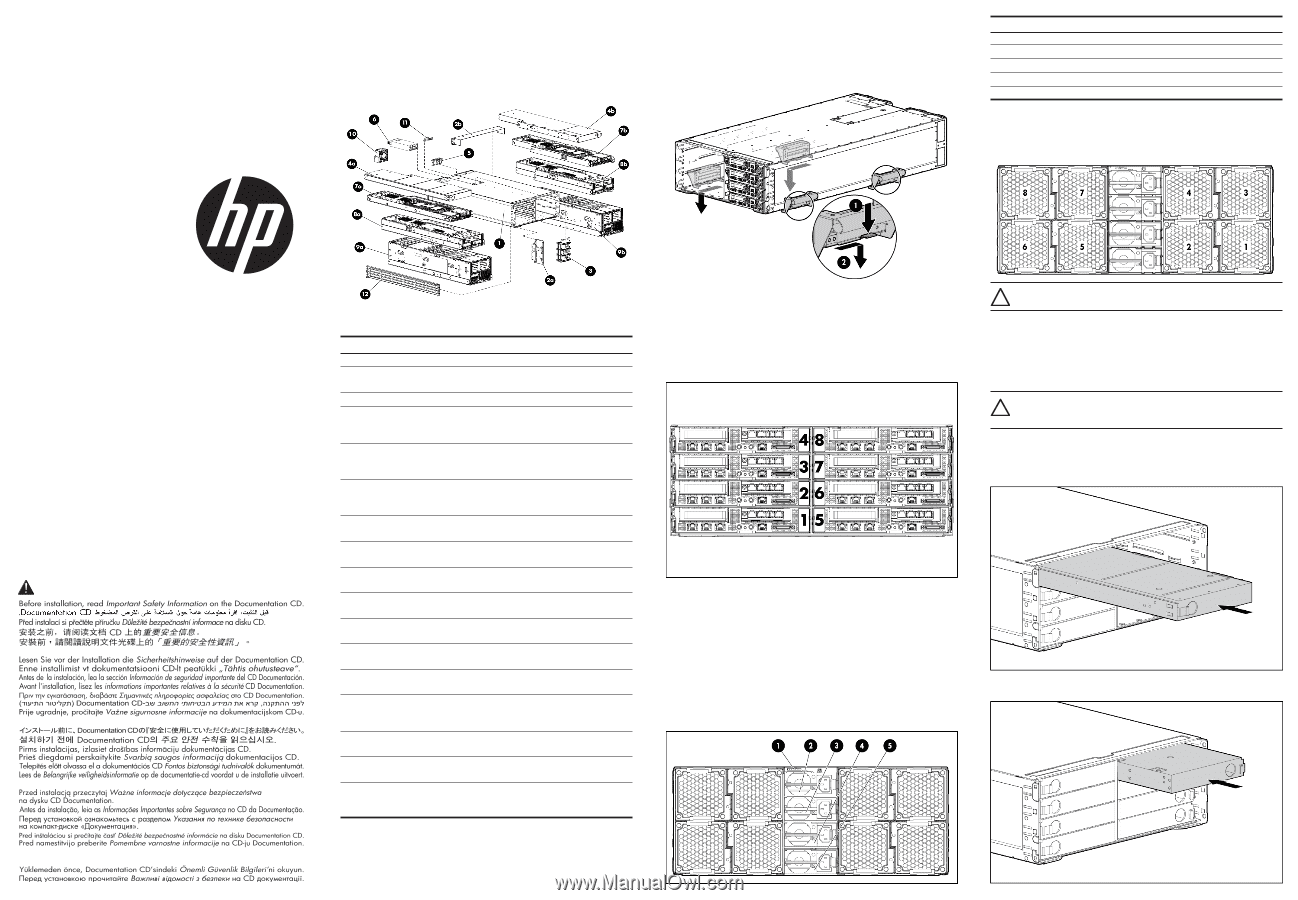
Verifying the pallet contents
Item
Name
Description
1
HP ProLiant s6500 Chassis
The HP ProLiant chassis
2a
Shipping brackets
Brackets used to secure the
2b
chassis
3
Power/data backplane board
—
4a
Device bay blank
A mandatory insert
installed in any unused
device bay, left node
4b
Device bay blank
A mandatory insert
installed in any unused
device bay, right node
5
Power supply blank
A mandatory insert
installed in any unused
power supply bay
6
High-efficiency power supply
The high-efficiency power
(quantity as ordered)
supply for the chassis
7a
1U server (quantity as ordered)
A 1U ProLiant SL server,
left node
7b
1U server (quantity as ordered)
A 1U ProLiant SL server,
right node
8a
2U server (quantity as ordered)
A 2U ProLiant SL server,
left node
8b
2U server (quantity as ordered)
A 2U ProLiant SL server,
right node
9a
4U server (quantity as ordered)
A 4U ProLiant SL server,
left node
9b
4U server (quantity as ordered)
A 4U ProLiant SL server,
right node
10
System fan (quantity as ordered)
A fan used to cool the
components installed in
the chassis
11
SL APM (optional)
An interface for SL system
administration
12
Rack rails (optional)
Rails used to install the
chassis into a rack
13*
Documentation CD
A CD containing detailed
documentation about using
the chassis
* Not shown
Setting up the chassis
1.
Select the proper location for the chassis to be set up, based on requirements
detailed in the
HP ProLiant s6500 Chassis Setup and Installation Guide
.
2.
Remove the packing materials from the pallet.
3.
Remove the chassis handles
4.
Place the chassis in the location selected in step 1.
Chassis component identification
Before installing front or rear components into the chassis, review chassis slot
numbering for each component.
Front panel components
The following figure identifies the slot numbering for the front panel of the chassis.
Configuration guidelines
•
Half-width and full-width trays cannot be mixed.
•
No 2U trays can reside in the middle two bays (slots 2–3 or slots 6–7).
•
Each half of the chassis can support any of the half-chassis configurations.
•
Any SL-series servers can be mixed within a chassis.
•
Empty bays must be populated with a node blank to meet thermal requirements.
•
Fans must be installed in all fan bays to meet thermal requirements.
•
Redundant and nonredundant fan configurations cannot be mixed.
Rear panel components
The server has four power supplies, eight fans, and a single SLAPM interface
located on the rear panel of the chassis.
Item
Description
1
SLAPM interface
2
Power supply 4
3
Power supply 3
4
Power supply 2
5
Power supply 1
System fans
The server has eight system fans located on the rear panel of the chassis.
The following figure identifies the system fans by device number in a nonredundant
configuration.
CAUTION:
To prevent damage to the server, do not install a combination
of redundant and non-redundant fans.
Installing the chassis into a rack
To install the chassis into a rack, see the
HP ProLiant s6500 Chassis Setup and
Installation Guide
. For additional details, see the instructions included with the
rail kit.
Installing the front components
CAUTION:
To prevent improper cooling and thermal damage, do not
operate the server or the enclosure unless all hard drive and device bays
are populated with either a component or a blank.
Add any ordered options to each node.
Half-width node blank kit installation
Installing the half-width node blank into the left tray
Installing the half-width node blank into the right tray
© Copyright 2012 Hewlett-Packard Development Company, L.P.
The information contained herein is subject to change without notice. The only
warranties for HP products and services are set forth in the express warranty
statements accompanying such products and services. Nothing herein should be
construed as constituting an additional warranty. HP shall not be liable for technical
or editorial errors or omissions contained herein.