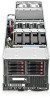
HP ProLiant SL270s HP ProLiant SL Servers Quick Setup Instructions - (January - Page 2
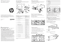
Installing the rear components, Cabling the chassis, Powering up the chassis, Configuring the chassis - gen8
 |
View all HP ProLiant SL270s manuals
Add to My Manuals
Save this manual to your list of manuals |
Page 2 highlights
Removing the center wall To support full-width tray configurations, remove the center wall. After removing the center wall, you can install full-width node or tray blanks. NOTE: Half-width and full-width server trays cannot be mixed within a chassis. 1. Loosen the screws that secure the center wall to the top of the chassis. 2. Loosen the screws that secure the center wall to the bottom of the chassis. 3. Slide the center wall in the direction of the arrow indicated in the following figure. Installing the system fan Insert the system fan into the chassis. Troubleshooting resources The HP ProLiant Gen8 Troubleshooting Guide, Volume I: Troubleshooting provides procedures for resolving common problems and comprehensive courses of action for fault isolation and identification, issue resolution, and software maintenance on ProLiant servers and server blades. The HP ProLiant Gen8 Troubleshooting Guide, Volume II: Error Messages provides a list of error messages and information to assist with interpreting and resolving error messages on ProLiant servers and server blades. The documents are on the Documentation CD and on the HP website (http://www.hp.com/go/proliantgen8/docs). The installation is complete. For more information For more detailed setup and configuration information, see the HP ProLiant SL Servers Solution Overview and the HP ProLiant s6500 Chassis Setup and Installation Guide. For safety information and regulatory notices, see the relevant chapter of the server user guide on the HP website (http://www.hp.com). 4. Rotate the center wall. 5. Remove the center wall from the chassis. 6. Install the full-width tray or blank. Installing the server into the chassis 1. Insert the system tray into the chassis. 2. Rotate the tray handle to lock (2U and 4U nodes only). Installing the power supply CAUTION: Always install either a hot-plug power supply or a power supply blank into each bay to maintain proper airflow and cooling in the server. Improper airflow can lead to thermal damage. CAUTION: Do not mix HP 1200W, HP 1200W High Efficiency, HP 750W, or HP 750W High Efficiency power supplies in one enclosure. Install only one type of power supply in a single enclosure. 1. Align the power supply edge card connector with the open slot of power supply cage. 2. Slide the power supply into the power supply bay until it clicks into place. NOTE: These figures represent nodes that can be installed in the chassis and might not depict your specific nodes. 3. Connect peripheral devices to the server. WARNING: To reduce the risk of electric shock, fire, or damage to the equipment, do not plug telephone or telecommunications connectors into RJ-45 connectors. WARNING: To reduce the risk of electric shock or damage to the equipment: • Do not disable the power cord grounding plug. The grounding plug is an important safety feature. • Plug the power cord into a grounded (earthed) electrical outlet that is easily accessible at all times. • Unplug the power cord from the power supply to disconnect power to the equipment. • Do not route the power cord where it can be walked on or pinched by items placed against it. Pay particular attention to the plug, electrical outlet, and the point where the cord extends from the server. Installing the rear components CAUTION: To prevent improper cooling and thermal damage, do not operate the enclosure unless all bays are populated with a component or a blank. Cabling the chassis For detailed information about cabling the chassis, see the HP ProLiant s6500 Chassis Setup and Installation Guide. Powering up the chassis 1. Connect the power cables to the power supplies. 2. Connect the power cables to the power source (UPS or wall outlet) or to an installed PDU. Configuring the chassis For further information on setting up and configuring your system, see the HP ProLiant s6500 Chassis Quick Setup Instructions and the HP ProLiant s6500 Chassis Setup and Installation Guide.
-
 1
1 -
 2
2
 |
 |
