HP ProLiant SL390s HP ProLiant SL390s G7 2U half width Server Installation She - Page 1
HP ProLiant SL390s - G7 Server Manual
 |
View all HP ProLiant SL390s manuals
Add to My Manuals
Save this manual to your list of manuals |
Page 1 highlights
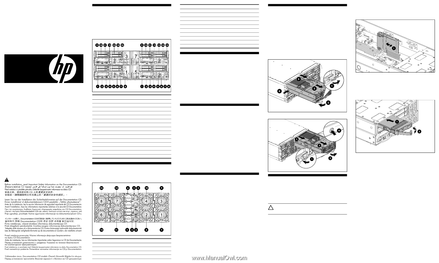
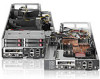
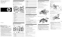
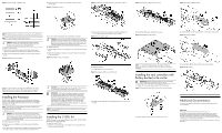
HP ProLiant SL390s G7 2U half width Server Installation Sheet Identifying Server Components Front Panel Components SL390s 2U Server Front Panel Components Figure 1 Front panel components of the s6500 chassis with 4 SL390s 2U servers Part number: 614093-001 June 2010 (First Edition) Important Safety Information Item 1 2 3 4 5 6 7 8 9 10 11 12 13 14 15 Description VGA port Serial port SFP PLUS connector QSFP NIC1/ iLO3 connector NIC2 connector USB connectors UID LED/SW HDD1 HDD2 Front PCIe bracket (LP slot) Power LED/SW HDD3 HDD4 iLO3 network port Rear Panel Components Figure 2 Rear panel components of the s6500 chassis with 4 SL390s 2U servers Læs dokumentet Vigtige sikkerhedsoplysninger på dokumentations-cd'en, før produktet installeres. Prima dell'installazione, leggere sul CD le Informazioni importanti sulla sicurezza. Les "Viktig sikkerhetsinformasjon" på dokumentasjons-CDen før du installerer dette produktet. Tärkeisiin turvatietoihin" Documentation CD -levyllä ennen tuotteen asentamista. Läs dokumentet Viktig säkerhetsinformation på dokumentations-cd:n innan du installerar denna produkt. Item 1 2 3 4 Description Power Supply 1 Power Supply 2 Power Supply 3 Power Supply 4 Item 5 6 7 8 9 10 11 12 13 14 Description UID LED APM connector Fan 1 Fan 2 Fan 3 Fan 4 Fan 5 Fan 6 Fan 7 Fan 8 Server Configuration Resources In addition to this Installation Sheet, other resources are available for more information regarding the configuration and maintenance of your server: • For safety information and detailed procedures relating to installation of options, refer to any installation instructions that came with the option, as well as the HP ProLiant SL390s G7 2U half width Server Maintenance and Service Guide. • For safety information, regulatory notices, and detailed procedures related to the rest of the steps listed in the "Configuring the Server" section, refer to the relevant chapter of the HP ProLiant SL390s G7 2U half width Server User Guide. • You can also access additional information and documentation from the HP website at http://www.hp.com/. Removing the Server You need to remove the server from the chassis before you can remove or replace a server component. To remove server: 1. Press the latch to release the handle. 2. Rotate the handle to disengage the power connector. 3. Extend the server from the chassis until the release latch catches. 4. Firmly holding the server, press the release button. 5. Remove the server from chassis. 6. Install the server blank in the server slot. Figure 3 Removing the SL390s left server To install 2 non-hotplug SFF hard disk drives or SSDs on quick release carriers to the tray: Figure 5 Installing the non-hotplug SFF hard disk drives or SSDs on quick release carriers to the tray To install 4 SFF hotplug hard disk drives or SSDs on hotplug driver carriers on the front of the tray: 1. Insert the HDD into the chassis. 2. Rotate the tray handle to lock the power connector. Figure 6 Installing the hotplug hard disk drives or SSDs on hotplug driver carrier on the front of the tray Server Configuration Overview The steps listed below give an overview of the necessary setup procedures for preparing the HP ProLiant SL390s Server for operation: 1. Connect the AC power cord and peripheral devices. 2. Power up the server. 3. Press "F9" to enter BIOS setup. 4. Note the server BIOS version. 5. Verify the server BIOS version against the latest BIOS version listed for this server on the HP website: http://www.hp.com. 6. If you do not have the latest BIOS, update the BIOS now. Refer to the HP ProLiant SL390s G7 2U half width Server User Guide available on the HP website: http://www.hp.com. 7. Install a supported operating system of your choice. For detailed procedures, refer to the documentation provided by the operating system vendor. For a list of operating systems supported by your ProLiant server, go to http://www.hp.com/go/supportos. Pre- and Post-installation Procedures When installing additional options in your HP ProLiant SL390s G7 2U half width server, observe the following procedures: Pre-installation procedures 1. Turn off the server and all the peripherals connected to it. 2. Remove the server from the chassis by following the procedure described later in the "Removing the server" section. Post-installation procedures 1. Be sure all components are installed according to the described step-by-step instructions. 2. Check to make sure you have not left loose tools or parts inside the server. 3. Reinstall the PCI riser, peripherals, and system cables that you have removed. 4. Reinstall the server into the chassis. 5. Connect all external cables to the system. 6. Press the power button on the front panel to turn on the server. Figure 4 Removing the SL390s right server Installing the Hard Disk Drive One SL390s 2U server tray can accommodate up to 6 SFF hard disk drives or SSDs, 2 non-hotplug SFF hard disk drives or SSDs on a quick release carrier attached internally to the tray, and 4 SFF hotplug hard disk drives or SSDs on the front of the tray. One chassis can accommodate 4 2U server trays for up to 24 SFF hard disk drives or SSDs. The server supports both SAS/SATA hard disk drives and SSDs. CAUTION: Drives can be damaged by static electricity. Before handling drives, touch an unpainted metal surface to discharge static electricity. Installing the Memory Module The following guidelines must be followed when memory modules are being added or replaced: • Support 12 DDR3 240-pin RDIMM (SR, DR, QR) or UDIMM (SR, DR) slots(6 DIMMs per CPU) • Channel 0 is located furthest to processor, followed by channel 1 then channel 2 • DIMM 0 is the furthest from the processor of the two DIMMs in a given channel • DIMM Capacity up to 16G • Speed is 800 MHz, 1067 MHz, 1333 MHz depending on DIMM population • DIMM Voltage is 1.5V and LV 1.35V • Support all valid DIMM configurations as long as the total node power is rated below the maximum value
-
 1
1 -
 2
2
 |
 |