HP ProLiant SL390s HP ProLiant SL390s G7 2U half width Server Installation She - Page 2
Installing the Processor, Installing the 3 GPU Kit, Installing the raid controllers with, Battery- - proliant sl390 gpu
 |
View all HP ProLiant SL390s manuals
Add to My Manuals
Save this manual to your list of manuals |
Page 2 highlights
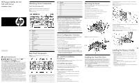
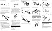
Figure 7 Population Order of DIMM Sockets 4. Close the processor socket retaining bracket and the processor retaining latch Figure 9 Installing the processor Figure 11 Installing the rear GPU assembly on the bottom of 2U tray Figure 14 Installing the 2 GPU shelf into the tray Figure 17 Installing the BBWC bracket NOTE: The DIMM should be installed from the furthest A channel DIMM slot. NOTE: It is recommended to install memory in pairs. CAUTION: DIMMs can be damaged by improper handling. Always use an anti-static wrist strap and grounding mat, and discharge static electricity before touching DIMMs. To install a memory module: 1. Align the notch on the bottom edge of the module with the keyed surface of the DIMM slot and then press the module fully into the slot. 2. Firmly press the holding clips inward to secure the memory module in place. Figure 8 Installing the memory module For processor removal, reverse the above installation procedures. CAUTION: To prevent the heat sink from tilting to one side during installation/removal, turn each screw a couple of turns, alternatively between both of them, and then apply the final torque. Do not over tighten the spring loaded screws to prevent them from breaking off. A maximum torque of 4.5 inch-lb is set for each screw. To install the heat sink: 1. Properly align the heat sink mounting pins to the system board mounting holes. 2. Tighten the mounting pins clockwise to secure the heat sink connection to the system board. Figure 10 Installing the heat sink assembly 2. Connect the PCA x24 riser card and the rear GPU assembly with 1.2.3.4 cables, make sure the cables connect correctly: Figure 12 Connecting the cables 3. Reinstall the HDD module and fasten the screws: Figure 15 Reinstalling the HDD module To install the 2 GPU Kit: 1. To install the GPUs to the 2 GPU shelf: Figure 13 Installing the GPUs on the 2 GPU shelf DIMM slots are structured to ensure proper installation. If you insert a DIMM but it does not fit easily into the slot, you may have inserted it incorrectly. Reverse the orientation of the DIMM and insert it again. Installing the Processor The HP ProLiant SL390s server supports Intel Nehalem and Westmere Processors High Wattage 95W,80W (Dual CPUs 64-bit), and Nehalem Processors Low Wattage 60W and Westmere Processor Low Wattage 40W(Dual CPUs 64-bit). NOTE: If one processor is being installed, it should be installed in the socket furthest from the IOH/chipset. To install the processor: CAUTION: Use the process install tool to insert the processor into the socket. The processor and system board spare part kits contain the processor install tool and instructions on how to use the tool. It is important to follow the instructions to prevent damage to the pins in the processor socket. 1. Insert the processor in the tool. 2. Align the processor installation tool with the socket and install the processor. 3. Press down firmly until the processor installation tool clicks and separates from the processor, and then remove the processor installation tool. CAUTION: Be sure that the heat sink sits squarely on the processor, or overheating and damage to the processor may occur. IMPORTANT: If the heat sink has been removed for any reason, it is critical that you apply more thermal interface material to the integrated heat spreader on the processor to ensure proper thermal bonding between the processor and the heat sink. Clean the contact surface of both the processor and heat sink with an alcohol pad, then re-apply an HP-approved thermal interface material before reinstalling the processor. Use a pattern of five dots when applying the thermal interface material-one dot in the center, and one dot at each corner. NOTE: Do not over tighten the heat sink's spring-loaded screws to prevent them from breaking off. Installing the 3 GPU Kit SL390s 2U server tray can support different kinds of GPU: P1030, M1060, M2050, M2070 and M2090 GPU. To install the Single GPU Kit: 1. Install the rear GPU assembly on the bottom of 2U tray and fasten the screws to secure it to the tray: 2. Install the 2 GPU shelf into the tray and fasten the screws to secure it to the tray: NOTE: For detailed information, refer to HP Single GPU Riser Kit Installation Instructions, HP SL390s 2 GPU Riser Option Kit Installation Instructions. Installing the raid controllers with Battery-backed write cache IMPORTANT: Remove the plastic bracket from the metal bracket before installing the plastic bracket into the chassis. 1. Unfasten the screws and lifting the plastic BBWC bracket out. Figure 16 Removing the plastic BBWC bracket from the metal bracket 2. Align the BBWC bracket to the tray and fasten the screws. 3. Install the BBWC into the tray and slide it in the direction of the arrow. Figure 18 Installing the BBWC 4. Connecting the BBWC cable with the smart array controllers. Figure 19 Cable routing Additional Documentation You can access additional information and documentation from the HP external website. Legal notices © Copyright 2010 Hewlett-Packard Development Company, L.P. The information contained herein is subject to change without notice. The only warranties for HP products and services are set forth in the express warranty statements accompanying such products and services. Nothing herein should be construed as constituting an additional warranty. HP shall not be liable for technical or editorial errors or omissions contained herein. Microsoft, Windows, and Windows NT are U.S. registered trademarks of Microsoft Corporation.
-
 1
1 -
 2
2
 |
 |
