HP R/T2200 IEC-320-C14 HP R/T2200 UPS Installation Instructions - Page 5
Selecting the UPS voltage configuration, Connecting the host computer
 |
View all HP R/T2200 IEC-320-C14 manuals
Add to My Manuals
Save this manual to your list of manuals |
Page 5 highlights
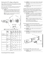
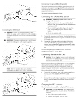
Selecting the UPS voltage configuration Using a small tool, position the DIP switches according to the desired voltage configuration and charge rate as identified on the rear panel of the UPS and in the following table. When using an ERM, set the Battery Charge Level switch (DIP switch 3) to the down position, increasing the UPS charger output and charging the ERM faster. CAUTION: Do not set the Battery Charge Level switch to the down position without an ERM connected. There is a risk of damaging the internal battery system of the UPS. NOTE: DIP switch 4 is inactive and does not affect UPS operation regardless of the position. NOTE: An asterisk (*) indicates the default setting. Output voltage Input DIP DIP DIP DIP voltage switch switch switch switch range 1 2 3 4 R/T2200 120 V* NA/JPN/TWN (NA) 108- Up Up Up* Up 127 V 110 V 99- Up Down - - 116 V 100 V* 90- Down Up - - (JPN/TWN) 106 V 120 V 108- Down Down Down Down 127 V R/T2200 INTL 230 V 20- Up Up Up* Up 7243 V 230 V* 207- Up Down - - (INTL) 243 V 220 V 198- Down Up - - 233 V 240 V 216- Down Down Down Down 254 V Connecting the host computer CAUTION: Use only the computer interface cable supplied with the UPS to connect the communications port to the host computer. CAUTION: Using a USB to serial converter cable will damage the UPS. Connect the UPS to a host computer using either the USB cable or the DB9 serial cable included with the UPS. Install HP Power Manager software 4.1 or later on the host computer. See the HP website (http://www.hp.com/go/rackandpower) to download the latest version of HP Power Manager. IMPORTANT: If using HPPM, connect the Management Server to an unswitched output receptacle, and then set the Management Server as the last device to shutdown, ensuring that all connected load devices are shutdown gracefully. NOTE: To install and configure the software, see the software user guide. The software user guide is available for download from the HP website (http://www.hp.com/go/rackandpower). Connecting the serial communications port CAUTION: Use only the computer interface cable supplied with the UPS to connect the communications port to the host computer. CAUTION: Using a USB to serial converter cable will damage the UPS. IMPORTANT: Power management software requires the communications port to be appropriately cabled to the host computer. Connecting the USB communications port CAUTION: Using a USB to serial converter cable will damage the UPS.
-
 1
1 -
 2
2 -
 3
3 -
 4
4 -
 5
5 -
 6
6 -
 7
7
 |
 |
