HP R/T2200 IEC-320-C14 HP R/T2200 UPS Installation Instructions - Page 6
Connecting the REPO port, Connecting the ground bonding cable, Connecting the UPS to utility power
 |
View all HP R/T2200 IEC-320-C14 manuals
Add to My Manuals
Save this manual to your list of manuals |
Page 6 highlights
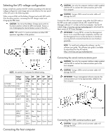
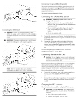
Connecting the REPO port WARNING: To meet the requirements stated in NEC (NFPA 70) Articles 645-10 and 645-11, a UPS installed in a computer equipment room must be connected to a REPO circuit. IMPORTANT: The remote switch must be in the Off (open) position to enable power to the output receptacles. NOTE: Wire the connector block using stranded, nonshielded wire (AWG #22 - #18, or equivalent). Connecting the ground bonding cable The ground bonding screw is provided as an attachment point for conductors. Use a ground bonding cable if the rack contains any conductors for the purpose of functional grounding or bonding of ungrounded metal parts. The ground bonding cable is not included. Connecting the UPS to utility power WARNING: To prevent injury from electric shock or damage to the equipment: • Plug the input line cord into a grounded (earthed) electrical outlet that is installed near the equipment and is easily accessible. • Do not disable the grounding plug on the input line cord. The grounding plug is an important safety feature. • Do not use extension cords. 1. Connect the input power cord from an intended load device to the IEC-320-C20 input power receptacle on the UPS rear panel (INTL model only). 2. Connect the UPS power cord to a grounded utility power outlet. When the UPS is plugged in, the batteries begin to charge. Power to the output receptacles designated for surge and battery backup is not available until the unit is powered up. For more information about receptacle control, see "Power management software" in the user guide. Connecting devices to the UPS CAUTION: Do not plug laser printers into the UPS output receptacles. The instantaneous current drawn by this type of printer can overload the UPS. Before connecting devices, verify that the UPS will not overload by checking that the ratings of the devices do not exceed the UPS capacity. If the equipment rating is listed in amps, multiply the number of amps by 120 (for Japan, by 100) to determine the VA. After verifying that the UPS will not overload: • Connect the device power cords to the output receptacles on the rear panel of the UPS (NA/JPN/TWN model). -or• Connect devices to the output receptacles on the rear panel of the UPS using the jumper cords included with the UPS (INTL model). Charging the UPS batteries Allow the batteries to charge before putting the UPS into service. IMPORTANT: Charge the batteries for at least 24 hours before supplying backup power to devices. The batteries charge to: • 90% of their capacity within 4 hours • 100% of their capacity within 24 hours
-
 1
1 -
 2
2 -
 3
3 -
 4
4 -
 5
5 -
 6
6 -
 7
7
 |
 |
