HP RP7 HP Retail RP7 VFD Customer Display Installation Instructions - Page 2
HP RP7 Manual
 |
View all HP RP7 manuals
Add to My Manuals
Save this manual to your list of manuals |
Page 2 highlights
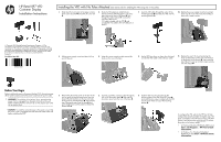
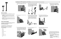
Installing the VFD Using One or Two Poles (see reverse side for installing the VFD with no poles attached) 1. Slide down the two levers on the upper corners of the rear I/O panel 1 and rotate the cover off 2. 4. Slide either one or two poles onto the mounting bracket, depending on the desired height of the VFD. Thread the extension cable through the top of the pole assembly and out the bottom of the mounting bracket 1. Connect the extension cable to the VFD cable 2, then slide the VFD onto the pole assembly 3. 7. Snap the decorative plate onto the rear of the base. 10. Replace the rear I/O cover by placing the hooks on the bottom of the cover into the slots on the bottom of the chassis 1. Then rotate the top of the I/O cover up so that it snaps securely onto the chassis 2. Before Your Begin Before installing the vacuum fluorescent display (VFD), be sure to power off the system and disconnect the power cord from the power outlet. WARNING! To avoid the risk of serious injury, ensure that the power cord is unplugged from the electrical outlet at the wall before installing the VFD. Failure to do so may expose you to the risk of electric shock. CAUTION: To avoid the risk of damage to the system, ensure that the power cord is unplugged from the electrical outlet at the wall before installing the VFD. 2. Pull the power supply cover back then lift if up and off the unit. 5. Route the VFD extension cable through the hole in the decorative panel that was included with the VFD, then through the rear of the base 1 and out the front of the base. Continue to route the extension cable up through the cable retainer 2 and connect the extension cable to the I/O cable included with the VFD 3. Connect the I/O cable to the 12V USB port on the RP7. 8. Slide the VFD mounting bracket into the mounting hole on the rear of the RP7 base 1, and install the two screws included with the VFD into the screw holes on top of the mounting bracket 2. Online Technical Support For the online access to technical support information, self-solve tools, online assistance, community forums or IT experts, broad multivendor knowledge base, monitoring and diagnostic tools, go to http://www.hp.com/support. Localized Versions of this Document Localized versions of this document are available at http://www.hp.com for the following languages: • Brazilian Portuguese • Dutch • English • French • German • Bahasa Indonesian • Italian • Japanese • Korean • Simplified Chinese • Spanish • Traditional Chinese • Thai 3. Remove the decorative panel on the rear of the unit by gently prying the panel away from the base at the tab locations on the top and sides of the panel as indicated below 1. Then pull the top of the panel away from the base 2 and push straight down on the panel to release the bottom tabs 3. 6. Wrap the excess extension cable around the hooks on the rear of the base. 9. Replace the power supply cover by lowering it down over the neck of the base then sliding it back until it snaps in place. To configure the VFD, refer to the HP Point of Sale Configuration Guide (available in English only). The guide is available on the HP factory image of the RP7 system's hard drive and at www.hp.com. To access the guide on the factory image: • In Windows Embedded POSReady 2009, select Start > All Programs > HP Point of Sale Information. • In Windows 7 or Windows Embedded POSReady 7, select Start > HP Point of Sale Information.
-
 1
1 -
 2
2
 |
 |
