HP SignagePlayer mp8000r Hardware Reference Guide
HP SignagePlayer mp8000r Manual
 |
View all HP SignagePlayer mp8000r manuals
Add to My Manuals
Save this manual to your list of manuals |
HP SignagePlayer mp8000r manual content summary:
- HP SignagePlayer mp8000r | Hardware Reference Guide - Page 1
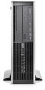
Hardware Reference Guide HP MP 8000r - HP SignagePlayer mp8000r | Hardware Reference Guide - Page 2
HP products and services are set forth in the express warranty statements accompanying such products and services. Nothing herein should be construed as constituting an additional warranty. HP -Packard Company. Hardware Reference Guide HP MP 8000r First Edition (June 2010) Document Part Number: 624910 - HP SignagePlayer mp8000r | Hardware Reference Guide - Page 3
About This Book This guide provides basic information for upgrading this computer model. WARNING! Text set off in this manner indicates that failure to follow directions could result in bodily - HP SignagePlayer mp8000r | Hardware Reference Guide - Page 4
iv About This Book - HP SignagePlayer mp8000r | Hardware Reference Guide - Page 5
Logo Key 6 Serial Number Location ...7 2 Hardware Upgrades ...8 Serviceability Features ...8 Warnings and Cautions ...8 Unlocking the Smart Cover Lock Removing Bezel Blanks ...14 Replacing the Front Bezel ...15 Using the HP MP 8000r in a Tower Orientation 16 Installing Additional Memory 17 DIMMs - HP SignagePlayer mp8000r | Hardware Reference Guide - Page 6
49 Appendix B Battery Replacement 51 Appendix C External Security Devices 54 Installing a Security Lock ...54 HP/Kensington MicroSaver Security Cable Lock 54 Padlock ...55 HP Player PC Security Lock 55 Front Bezel Security 57 Appendix D Electrostatic Discharge 59 Preventing Electrostatic - HP SignagePlayer mp8000r | Hardware Reference Guide - Page 7
run the diagnostic utility (included on some computer models only). NOTE: The HP MP 8000r can also be used in a tower orientation. For more information, see Using the HP MP 8000r in a Tower Orientation on page 16 in this guide. Figure 1-1 HP MP 8000r Configuration Standard Configuration Features 1 - HP SignagePlayer mp8000r | Hardware Reference Guide - Page 8
icon in the Windows taskbar. NOTE: The Power On Light is normally green when the power is on. If it is flashing red, there is a problem with the computer and it is displaying a diagnostic code. 2 Chapter 1 Product Features - HP SignagePlayer mp8000r | Hardware Reference Guide - Page 9
Media Card Reader Components The media card reader is an optional device available on some models only. Refer to the following illustration and table to identify the media card reader components. Figure 1-3 Media Card Reader Components Table 1-2 Media Card Reader Components No. Slot Media 1 xD - HP SignagePlayer mp8000r | Hardware Reference Guide - Page 10
Connector (blue) NOTE: Arrangement and number of connectors may vary by model. An optional second serial port and an optional parallel port are available from HP. When a device is plugged into the blue Line-In Audio Connector, a dialog box will pop up asking if you want to use the connector for - HP SignagePlayer mp8000r | Hardware Reference Guide - Page 11
Keyboard Figure 1-5 Keyboard Components Table 1-4 Keyboard Components 1 Function Keys Perform special functions depending on the software application being used. 2 Editing Keys Includes the following: Insert, Home, Page Up, Delete, End, and Page Down. 3 Status Lights Indicate the status of - HP SignagePlayer mp8000r | Hardware Reference Guide - Page 12
Using the Windows Logo Key Use the Windows Logo key in combination with other keys to perform certain functions available in the Windows operating system. Refer to Keyboard on page 5 to identify the Windows Logo key. Table 1-5 Windows Logo Key Functions The following Windows Logo Key functions - HP SignagePlayer mp8000r | Hardware Reference Guide - Page 13
Location Each computer has a unique serial number and product ID number in the location shown below. Keep these numbers available for use when contacting customer service for assistance. Figure 1-6 Serial Number and Product ID Location Serial Number Location 7 - HP SignagePlayer mp8000r | Hardware Reference Guide - Page 14
service. No tools are needed for most of the installation procedures described in this chapter. Warnings and Cautions Before performing upgrades be sure to carefully read all of the applicable instructions, cautions, and warnings in this guide This guide is located on the Web at http://www.hp.com/ - HP SignagePlayer mp8000r | Hardware Reference Guide - Page 15
HP reseller or service provider. Order PN 166527-001 for the wrench-style key or PN 166527-002 for the screwdriver bit key. ● Refer to the HP Web site (http://www.hp.com) for ordering information. ● Call the appropriate number listed in the warranty or in the Support Telephone Numbers guide - HP SignagePlayer mp8000r | Hardware Reference Guide - Page 16
6. Use the Smart Cover FailSafe Key to remove the tamper-proof screw that secures the Smart Cover Lock to the chassis. Figure 2-1 Removing the Smart Cover Lock Screw You can now remove the access panel. See Removing the Computer Access Panel on page 11. To reattach the Smart Cover Lock, secure the - HP SignagePlayer mp8000r | Hardware Reference Guide - Page 17
Removing the Computer Access Panel 1. Remove/disengage any security devices that prohibit opening the computer. 2. Remove all removable media, such as compact discs or USB flash drives, from the computer. 3. Turn off the computer properly through the operating system, then turn off any external - HP SignagePlayer mp8000r | Hardware Reference Guide - Page 18
Replacing the Computer Access Panel Slide the lip on the front end of the access panel under the lip on the front of the chassis (1) then press the back end of the access panel onto the unit so that it locks into place (2). Figure 2-3 Replacing the Access Panel 12 Chapter 2 Hardware Upgrades - HP SignagePlayer mp8000r | Hardware Reference Guide - Page 19
Removing the Front Bezel 1. Remove/disengage any security devices that prohibit opening the computer. 2. Remove all removable media, such as compact discs or USB flash drives, from the computer. 3. Turn off the computer properly through the operating system, then turn off any external devices. 4. - HP SignagePlayer mp8000r | Hardware Reference Guide - Page 20
Removing Bezel Blanks On some models, there are bezel blanks covering the 3.5-inch and 5.25-inch external drive bays that need to be removed before installing a drive. To remove a bezel blank: 1. Remove the access panel and front bezel. 2. To remove a bezel blank, push the two retaining tabs that - HP SignagePlayer mp8000r | Hardware Reference Guide - Page 21
Replacing the Front Bezel Insert the three hooks on the bottom side of the bezel into the rectangular holes on the chassis (1) then rotate the top side of the bezel onto the chassis (2) and snap it into place. Figure 2-6 Replacing the Front Bezel Replacing the Front Bezel 15 - HP SignagePlayer mp8000r | Hardware Reference Guide - Page 22
and place the computer in the optional stand. Figure 2-7 Changing from Desktop to Tower Orientation NOTE: To stabilize the computer in a tower orientation, HP recommends the use of the optional tower stand. 6. Reconnect the power cord and any external devices, then turn on the computer. NOTE: Ensure - HP SignagePlayer mp8000r | Hardware Reference Guide - Page 23
populated with up to four industry-standard DIMMs. These memory sockets are populated with at least one preinstalled DIMM. To achieve the maximum memory support, you can populate the system board with up to 16-GB of memory configured in a highperforming dual channel mode. DDR3-SDRAM DIMMs For proper - HP SignagePlayer mp8000r | Hardware Reference Guide - Page 24
Populating DIMM Sockets There are four DIMM sockets on the system board, with two sockets per channel. The sockets are labeled DIMM1, DIMM2, DIMM3, and DIMM4. Sockets DIMM1 and DIMM2 operate in memory channel A. Sockets DIMM3 and DIMM4 operate in memory channel B. Figure 2-8 DIMM Socket Locations - HP SignagePlayer mp8000r | Hardware Reference Guide - Page 25
populated with the least amount of memory describes the total amount of memory assigned to dual channel and the remainder is assigned to single channel. For optimal speed, the channels should be balanced so that the largest amount of memory is spread between the two channels. If one channel will - HP SignagePlayer mp8000r | Hardware Reference Guide - Page 26
7. Rotate up the external drive bay housing to access the memory module sockets on the system board. Figure 2-9 Rotating the Drive Cage Up 20 Chapter 2 Hardware Upgrades - HP SignagePlayer mp8000r | Hardware Reference Guide - Page 27
8. Open both latches of the memory module socket (1), and insert the memory module into the socket (2). Figure 2-10 Installing a DIMM NOTE: A memory module can be installed in only one way. Match the notch on the module with the tab on the memory socket. A DIMM must occupy the black DIMM1 socket. - HP SignagePlayer mp8000r | Hardware Reference Guide - Page 28
PCI expansion slot, two PCI Express x1 expansion slots, and one PCI Express x16 expansion slot. NOTE: The PCI and PCI Express slots support only low profile cards. Figure 2-11 Expansion Slot Locations Table 2-2 Expansion Slot Locations Item Description 1 PCI expansion slot 2 PCI Express x16 - HP SignagePlayer mp8000r | Hardware Reference Guide - Page 29
5. If the computer is on a stand, remove the computer from the stand. 6. Remove the access panel. 7. Locate the correct vacant expansion socket on the system board and the corresponding expansion slot on the back of the computer chassis. 8. Release the slot cover retention latch that secures the PCI - HP SignagePlayer mp8000r | Hardware Reference Guide - Page 30
9. Before installing an expansion card, remove the expansion slot cover or the existing expansion card. a. If you are installing an expansion card in a vacant socket, remove the appropriate expansion slot cover on the back of the chassis. Pull the slot cover straight up then away from the inside of - HP SignagePlayer mp8000r | Hardware Reference Guide - Page 31
b. If you are removing a standard PCI card or PCI Express x1 card, hold the card at each end, and carefully rock it back and forth until the connectors pull free from the socket. Pull the expansion card straight up from the socket (1) then away from the inside of the chassis to release it from the - HP SignagePlayer mp8000r | Hardware Reference Guide - Page 32
c. If you are removing a PCI Express x16 card, pull the retention arm on the back of the expansion socket away from the card and carefully rock the card back and forth until the connectors pull free from the socket. Pull the expansion card straight up from the socket then away from the inside of the - HP SignagePlayer mp8000r | Hardware Reference Guide - Page 33
12. To install a new expansion card, hold the card just above the expansion socket on the system board then move the card toward the rear of the chassis (1) so that the bracket on the card is aligned with the open slot on the rear of the chassis. Press the card straight down into the expansion - HP SignagePlayer mp8000r | Hardware Reference Guide - Page 34
16. If the computer was on a stand, replace the stand. 17. Reconnect the power cord and turn on the computer. 18. Lock any security devices that were disengaged when the access panel was removed. 19. Reconfigure the computer, if necessary. Drive Positions Figure 2-18 Drive Positions Table 2-3 Drive - HP SignagePlayer mp8000r | Hardware Reference Guide - Page 35
card. ● The system does not support Parallel ATA (PATA) optical drives or PATA hard drives. ● You must install guide screws to ensure the drive will line primary hard drive) use M3 metric screws. The HP-supplied metric screws are black and the HP-supplied standard screws are silver. If you are - HP SignagePlayer mp8000r | Hardware Reference Guide - Page 36
CAUTION: To prevent loss of work and damage to the computer or drive: If you are inserting or removing a drive, shut down the operating system properly, turn off the computer, and unplug the power cord. Do not remove a drive while the computer is on or in standby mode. Before handling a drive, - HP SignagePlayer mp8000r | Hardware Reference Guide - Page 37
Removing an External 5.25-inch Drive CAUTION: All removable media should be taken out of a drive before removing the drive from the computer. To remove a 5.25-inch external drive: 1. Remove/disengage any security devices that prohibit opening the computer. 2. Remove all removable media, such as - HP SignagePlayer mp8000r | Hardware Reference Guide - Page 38
8. If removing an optical drive, disconnect the power cable (1) and data cable (2) from the rear of the optical drive. Figure 2-22 Disconnecting the Power and Data Cables 9. Rotate the drive cage back down to its normal position. CAUTION: Be careful not to pinch any cables or wires when rotating the - HP SignagePlayer mp8000r | Hardware Reference Guide - Page 39
the drive cage (2). Figure 2-24 Removing the 5.25-inch Drive NOTE: To replace the drive, reverse the removal procedure. When replacing a drive, transfer the four guide screws from the old drive to the new one. Installing an Optical Drive into the 5.25-inch Drive Bay To install an optional 5.25-inch - HP SignagePlayer mp8000r | Hardware Reference Guide - Page 40
in the lower holes on each side of the drive. HP has provided four extra M3 metric guide screws on the front of the chassis, under the front bezel. The M3 metric guide screws are black. Refer to Installing and Removing Drives on page 29 for an illustration of the extra M3 metric - HP SignagePlayer mp8000r | Hardware Reference Guide - Page 41
of the drive cage. The other is located on the chassis frame under the drive cage. Ensure that the data cable is routed through these guides before connecting it to the optical drive. 13. Connect the power cable (1) and data cable (2) to the rear of the optical drive. Figure 2-28 Connecting - HP SignagePlayer mp8000r | Hardware Reference Guide - Page 42
14. Rotate the drive cage back down to its normal position. CAUTION: Be careful not to pinch any cables or wires when rotating the drive cage down. Figure 2-29 Rotating the Drive Cage Down 15. Replace the access panel. 16. If the computer was on a stand, replace the stand. 17. Reconnect the power - HP SignagePlayer mp8000r | Hardware Reference Guide - Page 43
2. Disconnect the drive cables from the rear of the drive, or, if you are removing a media card reader, disconnect the USB and 1394 cables from the system board as indicated in the following illustrations. NOTE: On some models, the media card reader does not include a 1394 port or cable. Figure 2-30 - HP SignagePlayer mp8000r | Hardware Reference Guide - Page 44
underneath the 5.25-inch drive. To install a drive into the 3.5-inch bay: NOTE: Install guide screws to ensure the drive will line up correctly in the drive cage and lock in place. HP has provided extra guide screws for the external drive bays (four 6-32 standard screws and four M3 metric screws - HP SignagePlayer mp8000r | Hardware Reference Guide - Page 45
3. Position the guide screws on the drive into the J-slots in the drive bay. Then slide the drive toward the front of the computer until it locks into - HP SignagePlayer mp8000r | Hardware Reference Guide - Page 46
Removing and Replacing the Primary 3.5-inch Internal SATA Hard Drive NOTE: The system does not support Parallel ATA (PATA) hard drives. Before you remove the old hard drive, be sure to back up the data from the old hard drive so - HP SignagePlayer mp8000r | Hardware Reference Guide - Page 47
8. Rotate the power supply to its upright position. The hard drive is located beneath the power supply. Figure 2-35 Raising the Power Supply 9. Disconnect the power cable (1) and data cable (2) from the back of the hard drive. Figure 2-36 Disconnecting the Hard Drive Power Cable and Data Cable - HP SignagePlayer mp8000r | Hardware Reference Guide - Page 48
and out of the bay (2). Figure 2-37 Removing the Hard Drive 11. To install a hard drive, you must transfer the silver and blue isolation mounting guide screws from the old hard drive to the new hard drive. Figure 2-38 Installing Hard Drive - HP SignagePlayer mp8000r | Hardware Reference Guide - Page 49
, be sure to route the SATA and power cables through the cable guide on the bottom of the chassis frame behind the hard drive. If the blue connector labeled SATA0 on the system board to avoid any hard drive performance problems. 14. Rotate the drive cage for external drives and the power supply down - HP SignagePlayer mp8000r | Hardware Reference Guide - Page 50
Removing and Replacing a Removable 3.5-inch SATA Hard Drive Some models are equipped with a Removable SATA Hard Drive Enclosure in the 5.25-inch external drive bay. The hard drive is housed in a carrier that can be quickly and easily removed from the drive bay. To remove and replace a drive in the - HP SignagePlayer mp8000r | Hardware Reference Guide - Page 51
3. Remove the adhesive strip that secures the thermal sensor to the top of the hard drive (1) and move the thermal sensor away from the carrier (2). Figure 2-41 Removing the Thermal Sensor 4. Remove the four screws from the bottom of the hard drive carrier. Figure 2-42 Removing the Security Screws - HP SignagePlayer mp8000r | Hardware Reference Guide - Page 52
5. Slide the hard drive back to disconnect it from the carrier then lift it up and out of the carrier. Figure 2-43 Removing the Hard Drive 6. Place the new hard drive in the carrier then slide the hard drive back so that it seats in the SATA connector on the carrier's circuit board. Be sure the - HP SignagePlayer mp8000r | Hardware Reference Guide - Page 53
7. Replace the four screws in the bottom of the carrier to hold the drive securely in place. Figure 2-45 Replacing the Security Screws 8. Place the thermal sensor on top of the hard drive in a position that does not cover the label (1) and attach the thermal sensor to the top of the hard drive with - HP SignagePlayer mp8000r | Hardware Reference Guide - Page 54
9. Slide the cover on the carrier (1) and replace the screw on the rear of the carrier to secure the cover in place (2). Figure 2-47 Replacing the Carrier Cover 10. Slide the hard drive carrier into the enclosure on the computer and lock it with the key provided. NOTE: The carrier must be locked for - HP SignagePlayer mp8000r | Hardware Reference Guide - Page 55
the desktop position) Height Width Depth 3.95 in 13.3 in 14.9 in 10.0 cm 33.8 cm 37.8 cm Approximate Weight 16.72 lb 7.6 kg Weight Supported (maximum distributed load in desktop position) 77 lb 35 kg Temperature Range Operating Nonoperating 50° to 95°F -22° to 140°F 10° to 35°C -30° to - HP SignagePlayer mp8000r | Hardware Reference Guide - Page 56
Table A-1 Specifications (continued) Power Supply 115V 230V Operating Voltage Range (STD PS) 90-264 VAC 90-264 VAC Operating Voltage Range (EPA 87/89/85% @ 20/50/100% load PS) 90-264 VAC 90-264 VAC Rated Voltage Range (STD PS) 100-240 VAC 100-240 VAC Rated Voltage Range (EPA 87/89/85% @ - HP SignagePlayer mp8000r | Hardware Reference Guide - Page 57
than 60°C (140ºF). Do not disassemble, crush, puncture, short external contacts, or dispose of in fire or water. Replace the battery only with the HP spare designated for this product. CAUTION: Before replacing the battery, it is important to back up the computer CMOS settings. When the battery is - HP SignagePlayer mp8000r | Hardware Reference Guide - Page 58
an internal component to gain access to the battery. 8. Depending on the type of battery holder on the system board, complete the following instructions to replace the battery. Type 1 a. Lift the battery out of its holder. Figure B-1 Removing a Coin Cell Battery (Type 1) b. Slide the replacement - HP SignagePlayer mp8000r | Hardware Reference Guide - Page 59
Type 3 a. Pull back on the clip (1) that is holding the battery in place, and remove the battery (2). b. Insert the new battery and position the clip back into place. Figure B-3 Removing a Coin Cell Battery (Type 3) NOTE: After the battery has been replaced, use the following steps to complete this - HP SignagePlayer mp8000r | Hardware Reference Guide - Page 60
C External Security Devices NOTE: For information on data security features, refer to the Desktop Management Guide and the HP ProtectTools Security Manager Guide (some models) at http://www.hp.com. Installing a Security Lock The security locks displayed below and on the following pages can be used - HP SignagePlayer mp8000r | Hardware Reference Guide - Page 61
Padlock Figure C-2 Installing a Padlock HP Player PC Security Lock 1. Fasten the security cable by looping it around a stationary object. Figure C-3 Securing the Cable to a Fixed Object Installing a Security Lock 55 - HP SignagePlayer mp8000r | Hardware Reference Guide - Page 62
2. Thread the keyboard and mouse cables through the lock. Figure C-4 Threading the Keyboard and Mouse Cables 3. Screw the lock to the chassis using the screw provided. Figure C-5 Attaching the Lock to the Chassis 56 Appendix C External Security Devices - HP SignagePlayer mp8000r | Hardware Reference Guide - Page 63
the lock. Figure C-6 Engaging the Lock Front Bezel Security The front bezel can be locked in place by installing a security screw provided by HP. To install the security screw: 1. Remove/disengage any security devices that prohibit opening the computer. 2. Remove all removable media, such as compact - HP SignagePlayer mp8000r | Hardware Reference Guide - Page 64
7. Remove one of the five silver 6-32 standard screws located on the front of the chassis behind the bezel. Figure C-7 Retrieving the Front Bezel Security Screw 8. Replace the front bezel. 9. Install the security screw next to the middle front bezel release tab to secure the front bezel in place. - HP SignagePlayer mp8000r | Hardware Reference Guide - Page 65
work mat. If you do not have any of the suggested equipment for proper grounding, contact an HP authorized dealer, reseller, or service provider. NOTE: For more information on static electricity, contact an HP authorized dealer, reseller, or service provider. Preventing Electrostatic Damage 59 - HP SignagePlayer mp8000r | Hardware Reference Guide - Page 66
E Computer Operating Guidelines, Routine Care and Shipping Preparation Computer Operating Guidelines and Routine Care Follow these guidelines to properly set up and care for the computer and monitor: ● Keep the computer away from excessive moisture, direct sunlight, and extremes of heat and cold. ● - HP SignagePlayer mp8000r | Hardware Reference Guide - Page 67
the finish. Safety If any object or liquid falls into the drive, immediately unplug the computer and have it checked by an authorized HP service provider. Shipping Preparation Follow these suggestions when preparing to ship the computer: 1. Back up the hard drive files on PD discs, tape cartridges - HP SignagePlayer mp8000r | Hardware Reference Guide - Page 68
installation guidelines 8 installing battery 51 drive cables 29 expansion card 22 guide screws 29 hard drive 40 media card reader 38 memory 17 optical in connector 4 line-out connector 4 locks cable lock 54 front bezel 57 HP Player PC Security Lock 55 padlock 55 Smart Cover Lock 9 M media card - HP SignagePlayer mp8000r | Hardware Reference Guide - Page 69
card reader 36 optical drive 31 PCI card 25 PCI Express card 26 Smart Cover Lock 9 S security cable lock 54 front bezel 57 HP Player PC Security Lock 55 padlock 55 Smart Cover Lock 9 serial connector 4 serial number location 7 shipping preparation 61 Smart Cover Lock 9 specifications computer 49
-
 1
1 -
 2
2 -
 3
3 -
 4
4 -
 5
5 -
 6
6 -
 7
7 -
8
-
9
-
10
-
11
-
12
-
13
-
14
-
15
-
16
-
17
-
18
-
19
-
20
-
21
-
22
-
23
-
24
-
25
-
26
-
27
-
28
-
29
-
30
-
31
-
32
-
33
-
34
-
35
-
36
-
37
-
38
-
39
-
40
-
41
-
42
-
43
-
44
-
45
-
46
-
47
-
48
-
49
-
50
-
51
-
52
-
53
-
54
-
55
-
56
-
57
-
58
-
59
-
60
-
61
-
62
-
63
-
64
-
65
-
66
-
67
-
68
-
69
 |
 |

Hardware Reference Guide
HP MP 8000r