HP StorageWorks 1606 HP StorageWorks 1606 Extension SAN Switch quick start ins - Page 1
HP StorageWorks 1606 - Extension SAN Switch Manual
 |
View all HP StorageWorks 1606 manuals
Add to My Manuals
Save this manual to your list of manuals |
Page 1 highlights
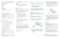
HP StorageWorks 1606 Extension SAN Switch quick start instructions © Copyright 2009 Hewlett-Packard Development Company, L.P. First edition: September 2009 The information in this document is subject to change without notice. Printed in the U.S. www.hp.com AP862-96001 Overview Read these instructions to set up and configure the HP StorageWorks 1606 Extension SAN Switch. These instructions provide basic configuration steps. For detailed rack mount and configuration instructions, download the HP StorageWorks 8Gb SAN Switch hardware reference guide from the Storage section of the following HP website: http://www.hp.com/support/manuals. Figure 1 shows the port side of the 1606 SAN Switch. Figure 1 Port side of the 1606 SAN Switch . 1. System Power LED 6. Fibre Channel ports (16) 2. System Status LED 7. GbE ports - copper RJ45(2) 3. Console port (RJ-45) 8. GbE ports - optical SFP (6) 4. Ethernet management port 9. Serial number pull-out tab 5. USB port Verify the carton contents Verify that the carton contains the following: • One 1606 SAN Switch with two integrated power supply/fan assemblies • One accessory kit with the following items: • Serial cable with an RJ-45 connector • Rubber feet, required to set up the switch as a standalone unit • Rack mount kit • HP StorageWorks product documentation, including HP StorageWorks SAN Rack Mount installation instructions, Read Me First, Safety Guides, User License, and Warranty • Two power cords. Verify the installation requirements To set up the 1606 SAN Switch for the first time, you will need the following: • Workstation with an installed terminal emulator (such as HyperTerminal) • Unused IP address and corresponding subnet mask and gateway address • Serial cable (supplied with the switch) • Ethernet cable • Access to an FTP server for backing up the switch configuration (optional) • SFP transceivers and cables IMPORTANT: Order transceivers or cables separately. The 1606 SAN Switch supports only transceivers and cables labeled B-series, SFP+, or cable. See http://www.hp.com for more information on supported transceivers. Plan the site environment To ensure adequate cooling, install the switch with the non-port side (which contains the air intake vents) facing the cool-air aisle. Verify that the ambient air temperature does not exceed 40°C (104°F) and that the ambient humidity remains between 20% and 85% while the switch is operating. To install and operate the switch successfully, ensure that: • The primary AC input is 100-240 VAC, 2.5 A-5.0A (the switch autosenses the input voltage), 47-63 Hz. • The primary outlet is wired correctly, protected by a circuit breaker, and grounded in accordance with local electrical codes. • The supply circuit, line fusing, and wire size are adequate, as specified by the electrical rating on the switch nameplate. For specific power supply information, see the HP StorageWorks 8Gb SAN Switch hardware reference guide. Choose the rack mount HP strongly recommends installing the switch in one of the following optional HP custom racks: • HP StorageWorks System/e Rack • HP StorageWorks 9000 Series Rack • HP StorageWorks 10000 Series Rack • HP StorageWorks 10000 G2 Series Rack Follow these guidelines: • Use one rack unit (1U) in a 48.3 cm (19 in) cabinet. • Ground all equipment in the rack through a reliable branch circuit connection, and maintain ground at all times. Do not rely on a secondary connection to a branch circuit, such as a power strip. • Ensure that airflow and temperature requirements are being met, especially if the switch is installed in a closed or multi-rack assembly. • Ensure that the additional weight of the switch does not exceed the rack's weight limits or unbalance the rack. • Secure the rack to ensure stability in case of unexpected movement. For additional installation, electrical, environmental, and other considerations, see the HP StorageWorks 8Gb SAN Switch hardware reference guide. Install a standalone switch 1. Unpack the switch and verify the contents as described in Verify the carton contents. 2. Apply the adhesive rubber feet to prevent the switch from sliding off the supporting surface. a. Clean the indentations at each corner on the bottom of the switch to ensure that they are free of dust or other debris. b. With the adhesive side against the chassis, place one rubber foot in each indentation and press into place. 3. Place the switch on a flat, sturdy surface. Set up a single-switch configuration NOTE: If you are installing the 1606 SAN Switch in a single-switch configuration, you can use EZSwitchSetup to complete the basic configuration. To set up a single-switch configuration, you will need the following: • Standard screwdriver • Fixed IP address (IPv4 or IPv6) for the switch (no DHCP server) • Subnet mask value • Default gateway value • World Wide Name (WWN), located on the switch ID pull-out tab • Ethernet connection (hub or switch) • Ethernet and Fibre Channel cables • Disk array with Fibre Channel ports • Browser that allows pop-up windows Power on the switch 1. Connect the power cords to both power supplies and then to power sources on separate circuits to protect against AC failure. 2. Power on the power supplies by flipping both AC switches to the position marked 1 (one). The power supply LEDs are amber until power-on self-test (POST) is complete, and then change to green. The 1606 SAN Switch takes one to three minutes to boot and complete POST. 3. After POST is complete, verify that the switch power and status LEDs on the port side of the switch are green. Connect the serial cable 1. Connect the serial cable to the serial port on the switch and to an RS-232 serial port on the workstation. If the serial port is RJ-45 instead of RS-232, remove the adapter on the end of the serial cable and insert the exposed RJ-45 connector into the RJ-45 serial port on the workstation. 2. Disable any serial communication programs running on the workstation.
-
 1
1 -
 2
2
 |
 |