HP StorageWorks 1606 HP StorageWorks 1606 Extension SAN Switch quick start ins - Page 2
Connect devices
 |
View all HP StorageWorks 1606 manuals
Add to My Manuals
Save this manual to your list of manuals |
Page 2 highlights
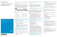
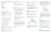
3. Open a terminal emulator (such as HyperTerminal on a PC, or TERM, TIP, or Kermit in a UNIX environment), and configure the application as follows: For most Windows systems: Bits per second: 9,600 Data bits: 8 Parity: None Stop bits: 1 Flow control: None For most UNIX systems: tip /dev/ttyb -9600 If ttyb is already in use, try ttya instead: tip /dev/ttya -9600 Log in to the serial console port 1. Verify that the switch has completed POST. When POST is complete, the port status, switch power, and status LEDs return to a normal state. 2. When the terminal emulator stops reporting information, press Enter to display the login prompt. 3. Log in to the switch as admin, using the default password, password. You are prompted to change the default password at initial login. Set a static IP address 1. Use the ipaddrset command to set the Ethernet IP address. • For an IPv4 address, use dotted-decimal notation: Ethernet IP Address: 192.168.74.102 • For an IPv6 address, use colon-separated notation: switch:admin> ipaddrset -ipv6 --add 1080::8:800:200C:417A/64 The following message confirms the change: IP address is being changed...Done. 2. Provide the remaining network information: Ethernet Subnetmask: 255.255.255.0 Ethernet IP Address: 192.168.74.102 Ethernet Subnetmask: 255.255.255.0 3. Optionally, verify the IP address by entering the ipaddrshow command at the prompt. 4. Record the IP address on the pull-out tab on the port side of the switch. 5. When prompted, enter off to disable the Dynamic Host Configuration Protocol (DHCP): DHCP [OFF]: off 6. If the serial port is no longer required, use the logout command to log out of the serial console. Remove the serial cable and replace the plug in the serial port. 7. Connect the Ethernet port on the switch to the Ethernet network that has just assigned the IP address. NOTE: DHCP is supported. See the HP StorageWorks 8Gb SAN Switch Hardware Reference Manual to set up DHCP. Set the date and time The date and time settings are used for logging, error detection, and troubleshooting. 1. Using a Telnet or Secure Shell (SSH) session, connect to the switch using the IP address that you configured and then log in to the switch as admin, using the default password, password. 2. Enter the date command using the following syntax: date "mmddHHMMyy" • mm is the month; valid values are 01 through 12. • dd is the date; valid values are 01 through 31. • HH is the hour; valid values are 00 through 23. • MM is minutes; valid values are 00 through 59. • yy is the year; valid values are 00 through 99. 3. Enter the tstimezone command: switch:admin> tstimezone [--interactive]/ [, timezone_fmt] Use timezone_fmt to set the time zone by country/city or by time-zone ID, such as PST. The following example shows how to change the time zone to US/Central. switch:admin> tstimezone Time Zone : US/Pacific switch:admin> tstimezone US/Central switch:admin> tstimezone Time Zone : US/Central 4. Enter the tsClockServer command to synchronize local time: switch:admin> tsclockserver "" The value of ntp1 is the IP address or DNS name of the first NTP server, which the switch must be able to access. The value of ntp2 is the second NTP server and is optional. When multiple NTP server addresses are specified, tsclockserver sets the first obtainable address as the active NTP server. The default value is LOCL. switch:admin> tsclockserver LOCL switch:admin> tsclockserver "132.163.135.131" switch:admin> tsclockserver 132.163.135.131 switch:admin> Configure the zones, and perform device selection 1. Select Typical Zoning on the Zone Configuration screen. Click Next. NOTE: Typical Zoning is the default zone configuration. See the EZSwitchSetup Administrator's Guide for more information on zone configuration. 2. Enter the number and types of devices that you are connecting to the switch as shown on the Device Selection screen. EZSwitchSetup uses these values to automatically configure the ports on your switch for the devices that you are connecting. Connect devices The Connect Devices screen opens a graphical representation of the switch with the device connections based on the information that you entered in Configure the zones, and perform device selection. NOTE: The Connect Devices screen shows all physical connections as missing until you connect the devices that you specified. The following process applies to FCIP ports as well as FC ports. 1. Install the SFP transceivers in the Fibre Channel ports on the switch to match the ports shown onscreen (see Figure 2). Figure 2 Installing SFP transceivers in Fibre Channel ports . a. Remove any protector plugs from the SFP transceiver. Insert each SFP transceiver as required (right side up in the top row of ports, and upside down in the bottom row of ports) until it is firmly seated. b. Close the latching bale. 2. Connect Fibre Channel cables from the switch (see Figure 3) to your host and storage devices (not shown). Make the physical connections to match the connections on the Device Connection screen. a. Remove plastic protector caps from the Fibre Channel cable ends (if there are any), and position the cable connector so that it is oriented correctly. b. Insert the cable connector into the SFP until it is firmly seated and the latching mechanism clicks (see Figure 3). Figure 3 Inserting cable connectors into SFPs . c. If you have chosen to use the copper option for FCIP GbE ports ge0 and ge1, you can make those connections now as well. d. The Device Connection screen shows missing, valid, and invalid connections as you cable the switch. Note that it can take up to 15 seconds for the window to display the connection valid. Verify that the connections display green and click Next. 3. The Finish screen appears, indicating that setup is complete. 4. Click Finish to exit setup. Verify operation To verify switch operation: 1. Check the LEDs to verify that all components are functional. For information about LED patterns, refer to the HP StorageWorks 8Gb SAN Switch hardware reference guide. 2. Verify the correct operation of the 8Gb SAN Switch by issuing the switchShow command. This command provides information about switch and port status. 3. Verify the correct operation in the fabric by issuing the fabricShow command. This command provides general information about the fabric. 4. Back up the switch configuration to an FTP server by issuing the configUpload command and following the prompts. This command uploads the switch configuration to the server, making it available for downloading to a replacement switch if necessary. Set features This completes the initial setup of your 1606 SAN Extension Switch. See the Fabric OS 6.3.x administrator guide and the Fabric OS 6.3.x command reference manual for detailed instructions on setting features.
-
 1
1 -
 2
2
 |
 |