HP SureStore 7400 Power Supply System/Configuration Specific Instructions - Page 3
Step 9, Step 10, Step 11
 |
View all HP SureStore 7400 manuals
Add to My Manuals
Save this manual to your list of manuals |
Page 3 highlights
Step 9 Tighten the cam lever screws 9A in Figure 1). Step 10 Re-connect power cord. Step 11 Monitor the power supply LEDs (A & B in Figure 2). Green LED (A) indicates that the power supply is functioning. See Table 1 for full details of power supply LED behaviors. Figure 2: Power Module LEDs (Upper: Controller Enclosure; Lower: Disk Enclosure) A B A B Table 1: Power Module LEDs Status Indications A Power On LED (Green) Off On Off On * B Power Fault LED (Amber) Off Off On On Flashing Indication Power module not under power. Power module under power and operating normally. Power module fault. Power module fault (rare indication). Host identifying power module. *Can be on, off, or flashing 3
-
 1
1 -
 2
2 -
 3
3 -
 4
4
 |
 |

3
Step 9
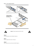
Tighten the cam lever screws 9A in Figure 1).
Step 10
Re-connect power cord.
Step 11
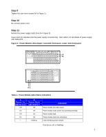
Monitor the power supply LEDs (A & B in Figure 2).
Green LED (A) indicates that the power supply is functioning.
See Table 1 for full details of power supply
LED behaviors.
Figure 2:
Power Module LEDs (Upper: Controller Enclosure; Lower: Disk Enclosure)
Table 1: Power Module LEDs Status Indications
A
Power On
LED (Green)
B
Power Fault
LED (Amber)
Indication
Off
Off
Power module not under power.
On
Off
Power module under power and operating normally.
Off
On
Power module fault.
On
On
Power module fault (rare indication).
*
Flashing
Host identifying power module.
*Can be on, off, or flashing
A
B
A B