HP rp7440 Site Preparation Guide, Fourth Edition - HP Integrity rx7640 and HP - Page 26
PCI-X/PCIe Backplane
 |
View all HP rp7440 manuals
Add to My Manuals
Save this manual to your list of manuals |
Page 26 highlights
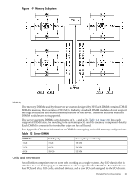
Table 1-5 PCI-X Slot Types I/O Partition Slot1 Maximum MHz Maximum Peak Ropes Bandwidth Supported Cards PCI Mode Supported 0 8 133 533 MB/s 001 3.3 V PCI or PCI-X Mode 1 7 133 1.06 GB/s 002/003 3.3 V PCI or PCI-X Mode 1 6 266 2.13 GB/s 004/005 3.3 V or 1.5 V PCI-X Mode 2 5 266 2.13 GB/s 006/007 3.3 V or 1.5 V PCI-X Mode 2 4 266 2.13 GB/s 014/015 3.3 V or 1.5 V PCI-X Mode 2 3 266 2.13 GB/s 012/013 3.3 V or 1.5 V PCI-X Mode 2 2 133 1.06 GB/s 010/011 3.3 V PCI or PCI-X Mode 1 1 133 1.06 GB/s 008/009 3.3 V PCI or PCI-X Mode 1 1 8 133 533 MB/s 001 3.3 V PCI or PCI-X Mode 1 7 133 1.06 GB/s 002/003 3.3 V PCI or PCI-X Mode 1 6 266 2.13 GB/s 004/005 3.3 V or 1.5 V PCI-X Mode 2 5 266 2.13 GB/s 006/007 3.3 V or 1.5 V PCI-X Mode 2 4 266 2.13 GB/s 014/015 3.3 V or 1.5 V PCI-X Mode 2 3 266 2.13 GB/s 012/015 3.3 V or 1.5 V PCI-X Mode 2 2 133 1.06 GB/s 010/011 3.3 V PCI or PCI-X Mode 1 1 133 1.06 GB/s 008/009 3.3 V PCI or PCI-X Mode 1 1 Each slot will auto select the proper speed for the card installed up to the maximum speed for the slot. Placing high speed cards into slow speed slots will cause the card to be driven at the slow speed. PCI-X/PCIe Backplane The 16-slot (8 PCI and PCI-X; 8 PCI-Express) mixed PCI-X/PCI-Express ("PCI-X/PCIe") I/O backplane was introduced for the Dual-Core Intel® Itanium® processor 9100 Series release and is heavily leveraged from the PCI-X backplane design. Only the differences will be descibed here.See "I/O Subsystem" (page 23) for common content between the two boards. The PCI-Express I/O backplane comprises two logically independent I/O circuits (partitions) on one physical board. • The I/O chip in cell location zero (0) and its associated four PCI-X ASICs, four PCIe ASICs, and their respective PCI/PCI-X/PCIe slots form PCI-Express I/O partition 0 plus core I/O. • The I/O chip in cell location one (1) and its associated four PCI-X ASICs, four PCIe ASICs, and their respective PCI/PCI-X/PCIe slots form PCI-Express I/O partition 1 plus core I/O. Each PCI/PCI-X slot has a host-to-PCI bridge associated with it, and each PCIe slot has a host-to-PCIe bridge associated with it. A dual slot hot swap controller chip and related logic is also associated with each pair of PCI or PCIe slots. The I/O chip on either cell location 0 or 1 is a primary I/O system interface. Upstream, the I/O chips communicate directly with the cell controller ASIC on the host cell board via a high bandwidth logical connection known as the HSS link.When installed in the SEU chassis within a fully configured system, the ASIC on cell location 0 connects 26 HP Integrity rx7640 Server and HP 9000 rp7440 Server Overview
-
 1
1 -
2
-
3
-
4
-
5
-
6
-
7
-
8
-
9
-
10
-
11
-
12
-
13
-
14
-
15
-
16
-
17
-
18
-
19
-
20
-
 21
21 -
 22
22 -
 23
23 -
 24
24 -
 25
25 -
 26
26 -
 27
27 -
 28
28 -
 29
29 -
 30
30 -
 31
31 -
32
-
33
-
34
-
35
-
36
-
37
-
38
-
39
-
40
-
41
 |
 |
