Hitachi 57T500 Owners Guide - Page 14
Connecting External Audio Devices, Connecting External Video Sources - manual
 |
View all Hitachi 57T500 manuals
Add to My Manuals
Save this manual to your list of manuals |
Page 14 highlights
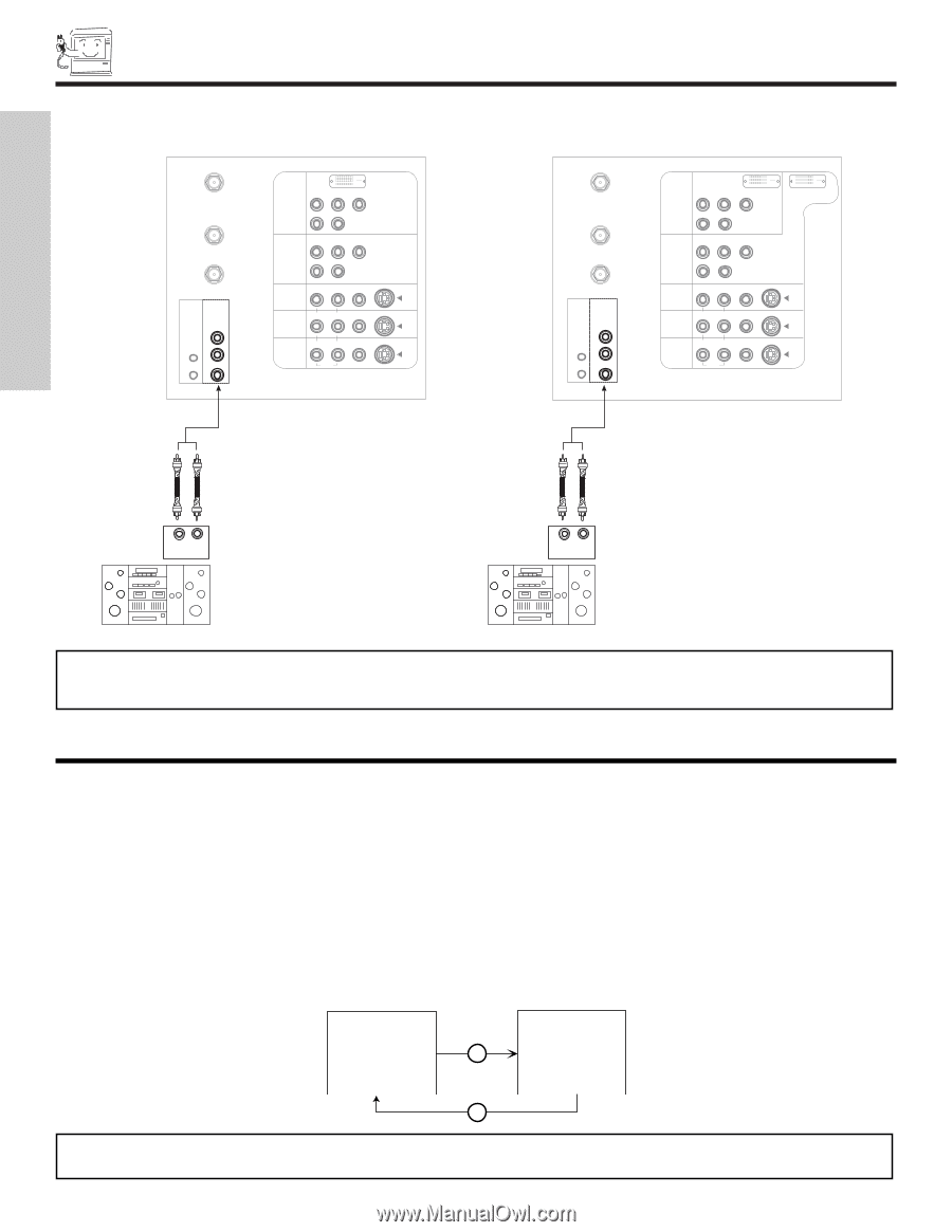
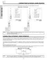
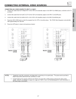
FIRST TIME USE CONNECTING EXTERNAL AUDIO DEVICES To control the audio level of an external audio amplifier with the remote control, connect the system as shown below. ANT A TO CONVERTER ANT B AUDIO TO HI-FI CENTER IN IR BLASTER L R REAR PANEL OF TELEVISION INPUT 1 INPUT 2 DVI-HDTV PR PB Y R (MONO)/L AUDIO PR PB Y/VIDEO R (MONO)/L AUDIO ANT A TO CONVERTER ANT B INPUT 3 R (MONO)/L VIDEO INPUT 4 R (MONO)/L VIDEO MONITOR OUT R L VIDEO AUDIO S-VIDEO S-VIDEO S-VIDEO AUDIO TO HI-FI CENTER IN IR BLASTER L R INPUT 1 INPUT 2 PR PB Y DVI-HDTV R (MONO)/L AUDIO PR PB Y/VIDEO R (MONO)/L AUDIO DVI-HDTV INPUT 3 R (MONO)/L VIDEO S-VIDEO INPUT 4 R (MONO)/L VIDEO S-VIDEO MONITOR OUT R L AUDIO VIDEO S-VIDEO Models: 57T500 65T500 Models: 57X500 65X500 LR INPUT LR INPUT Stereo System Amplifier Stereo System Amplifier NOTE: 1. To prevent damage to the speaker and distorted sound, set the volume control of the audio amplifier lower and adjust the sound using the remote control of the TV set. 2. See page 51 for AUDIO Settings. CONNECTING EXTERNAL VIDEO SOURCES The exact arrangement you use to connect the VCR, camcorder, laserdisc player, DVD player, or HDTV Set Top Box to your TV set is dependent on the model and features of each component. Check the owner's manual of each component for the location of video and audio inputs and outputs. The following connection diagrams are offered as suggestions. However, you may need to modify them to accommodate your particular assortment of components and features. For best performance, video and audio cables should be made from coaxial shielded wire. Before Operating External Video Source The input mode is changed every time the VID1~VID5 button is pressed as shown below. Connect an external source to the INPUT terminal, then press the VID1~VID5 button as necessary to view the input source (see page 33). INPUT MODE SELECTION ORDER (ANTENNA) (INPUT) Ant A VID1 YPBPR:1 VID1 ANT NOTE: When the TV is set to VIDEO and a video signal is not received from the VIDEO INPUT JACK on the back panel of the TV (i.e., VCR/laserdisc player, etc. is not connected or the video device is OFF), the set will appear to be OFF. 14
-
 1
1 -
2
-
3
-
4
-
5
-
6
-
7
-
8
-
 9
9 -
 10
10 -
 11
11 -
 12
12 -
 13
13 -
 14
14 -
 15
15 -
 16
16 -
 17
17 -
 18
18 -
 19
19 -
20
-
21
-
22
-
23
-
24
-
25
-
26
-
27
-
28
-
29
-
30
-
31
-
32
-
33
-
34
-
35
-
36
-
37
-
38
-
39
-
40
-
41
-
42
-
43
-
44
-
45
-
46
-
47
-
48
-
49
-
50
-
51
-
52
-
53
-
54
-
55
-
56
-
57
-
58
-
59
-
60
-
61
-
62
-
63
-
64
-
65
-
66
-
67
-
68
-
69
-
70
-
71
-
72
-
73
-
74
-
75
-
76
-
77
-
78
-
79
-
80
 |
 |