Hitachi NR90GC Service Manual
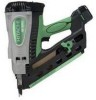
Hitachi NR90GC - 3-1/2" Gas Powered Clipped Head Framing Nailer Manual
 |
UPC - 717709008533
View all Hitachi NR90GC manuals
Add to My Manuals
Save this manual to your list of manuals |
Hitachi NR90GC manual content summary:
- Hitachi NR90GC | Service Manual - Page 1
MODEL NR 90GC Hitachi Power Tools GAS STRIP NAILER NR 90GC TECHNICAL DATA AND SERVICE MANUAL N LIST No. E025 Sept. 2005 SPECIFICATIONS AND PARTS ARE SUBJECT TO CHANGE FOR IMPROVEMENT - Hitachi NR90GC | Service Manual - Page 2
REMARK: Throughout this TECHNICAL DATA AND SERVICE MANUAL, a symbol is used in the place of company name and model name of our competitor. The symbol utilized here is as follows: Symbols Utilized P Competitors Company Name Paslode Model Name IMCT - Hitachi NR90GC | Service Manual - Page 3
Instructions ...6 7-2. Warning Label ...6 7-3. Related Laws and Regulations ...8 8. MECHANISM AND OPERATION PRINCIPLE 10 8-1. Mechanism ...10 8-2. Principle of Operation ...12 9. TROUBLESHOOTING GUIDE ...16 9-1. Problems 69 12. STANDARD REPAIR TIME (UNIT) SCHEDULES 70 Assembly diagram for NR 90GC - Hitachi NR90GC | Service Manual - Page 4
market with the new Model NR 90GC gas strip nailer to expand our market share. The main features of the Model NR 90GC are as follows: (1) The battery is located at the end of the handle for well balance. (2) New aggressive appearance (3) 2-actioned nail feeding (4) Comfortable grip (5) Fully charged - Hitachi NR90GC | Service Manual - Page 5
No. 317918) - For Europe Lubricant oiler (A) (Code No. 885246) Fuel cell (Code No. 753600) Grease (Code No. 317918) 5-2. Explanation of the Nailing Action To meet the requirements of "ANSI SNT-101-2002" (USA), the Model NR 90GC is equipped with FULL SEQUENTIAL ACTUATION MECHANISM. FULL SEQUENTIAL - Hitachi NR90GC | Service Manual - Page 6
damage to the nailer. Also avoid use of misaligned nails or nails collated with a weak paper tape. Do not use P's 2" Roundrive nail (eccentric full round head nail) with the Model NR 90GC because it may cause bending of nails. It is recommended to use genuine HITACHI nails to ensure satisfactory - Hitachi NR90GC | Service Manual - Page 7
and the gas nailer Model NR 90GC on the output energy range. The output energy of the Model NR 90GC changes within the operating range from 5.7 kg/cm2 (81.5 psi) to 6.1 kg/cm2 (87.2 psi) as a result of conversion to the air pressure of the pneumatic nailer Model NR 90AD. Choose suitable nails and - Hitachi NR90GC | Service Manual - Page 8
6. COMPARISONS WITH SIMILAR PRODUCTS Maker HITACHI Model NR 90GC Weight (tool, battery, fuel cell) 3.5 kg (7.7 lbs.) Dimensions (L x H x W) 347 mm x 353 mm x 108 mm (12-21/32" x 13-29/32" x 4-1/4") Nail capacity 37 nails (1 strip) Magazine type Rear loading Driving depth adjusting - Hitachi NR90GC | Service Manual - Page 9
use of the Model NR 90GC Nailer by all of our customers, it is very important that at the time of sale the salesperson carefully ensures that the buyer seriously recognizes the importance of the contents of the Handling Instructions, and fully understands the meaning of the precautions listed on the - Hitachi NR90GC | Service Manual - Page 10
For Europe Fuel cell For the U.S.A. and Canada OK Befestigung D-47802 Krefeld, Germany www.okbefestigung.de PATENT PENDING well ventilated place. • No smoking. KEEP AWAY FROM SKIN AND EYES and DO NOT BREATHE GAS, for SKIN AND EYE IRRITANT and VAPOR HARMFUL. DO NOT REFILL. For EU OK Befestigung D- - Hitachi NR90GC | Service Manual - Page 11
drive nails and staples, there is an ever-present danger of misfiring and subsequent possible serious injury. Accordingly, close attention in handling is absolutely necessary at all times. Carefully ensure that the customer is fully aware of the precautions listed in the Handling Instructions - Hitachi NR90GC | Service Manual - Page 12
fuel gas; (3) After the remaining fuel gas has been discharged, to discharge remaining propellant gas must not take more than 20 m2 of room surface. A fire extinguisher of 6 kg, class A, B, C must be flame and sparks. Do not puncture or open the fuel cell. Keep out of reach of children. Carton box, - Hitachi NR90GC | Service Manual - Page 13
that of a pneumatic nailer except the magazine section. The Model NR 90GC is equipped with a fuel cell and a battery in order to output combustion energy in addition to the electric components such as electric circuits, motor and electric switches. As illustrated in Fig. 8, the Model NR 90GC can be - Hitachi NR90GC | Service Manual - Page 14
Cylinder Head [14] Spark Plug (A) [11] Motor Spring [12] Fan [20] Combustion chamber Chamber [24] Motor Mount [8] Top Cover [3] Motor [6] Cell Cover [109] Cell Lever [105] Switch Lever (B) [114] Cylinder Ass'y [42] Housing Ass'y [74] Piston [39] Battery [111] Piston Bumper [40] Pushing Lever - Hitachi NR90GC | Service Manual - Page 15
105] to rotate it. Thus the Cell Lever [105] pushes the back of the fuel cell to Combustion chamber O-ring [36] spray fuel into the combustion chamber. Chamber [24] Tension Plate [113] Convex of Chamber [24] Fig. 4 Switch Plate [34] Fuel cell Trigger [98] Cell Lever [105] Chamber [24] Trigger - Hitachi NR90GC | Service Manual - Page 16
fuel is almost completed. Nail Fig. 6 Switch Lever (B) [114] Switch Trigger [98] (3) During return When the Trigger [98] is depressed, the Chamber O-ring is sealed by the O-rings [15] and [36] to cut off the atmosphere Chamber [24] (Fig. 7). Because combustion gas is partially released into - Hitachi NR90GC | Service Manual - Page 17
Fan [20] rotates, air passes through the Filter [4], enters the combustion chamber and goes to the outside O-ring [36] Chamber [24] in order to discharge gas and cool the combustion chamber (Fig. 8). O-ring [15] Fan [20] Trigger [98] Pushing Lever [64] Chamber Lock Bar [100] Fig. 8 --- 14 - Hitachi NR90GC | Service Manual - Page 18
to the uppermost position. Then the nailer operates only when the Trigger [98] is depressed. The nailer does not operate if the pressing Switch Lever (B) [114] from Pushing Lever [64] rotating (Fig. 10). The switch is turned on and nails are driven by depressing the Trigger [98]. Fig. 9 Switch - Hitachi NR90GC | Service Manual - Page 19
9. TROUBLESHOOTING GUIDE 9-1. Problems Caused by Improper Handling Following table shows the problems that are apt to occur. These problems are not caused by abnormality of the nailer but improper handling. Please instruct the customers to use the nailer properly according to the table. Improper - Hitachi NR90GC | Service Manual - Page 20
the gas cartridge. Adapter Stem Fuel cell Adapter Stem Fuel cell Fig. 14 (2) Press forward (stem side) and downward on the front side of the metering valve. (3) Press downward on the rear of the metering valve until it seals. Fig. 15 Checking the fuel cell Problem Possible cause Fuel is - Hitachi NR90GC | Service Manual - Page 21
Problem Fuel is sprayed but no combustion occurs. Possible cause Inspection method The oxygen content of the air is low in a place such as highlands at an altitude of 1500 meters or more. A large amount of fuel is sprayed. Remedy Use the nailer in a place - Hitachi NR90GC | Service Manual - Page 22
the fuel cell is set properly. Short of fuel in the fuel cell. The metering valve is not set properly to the fuel cell. The Cell Lever [105] is deformed. The Adapter [30] is damaged. The Pushing Lever [64] cannot be pushed up. The battery indicator light does not light. The Motor - Hitachi NR90GC | Service Manual - Page 23
The wire must not be pinched when depressing the Trigger [98]. Spark plug cable Controller [101]. Controller connector Fig. 16 Motor wire connector Fig. 17 --- 20 --- - Hitachi NR90GC | Service Manual - Page 24
the nailer at high speed. Speed: 1 nail/sec. Continuous operation: 1000 nails/h Abnormal noise is heard when the fan is rotating. * A rubbing noise may be heard in some rare cases but there is no problem in operation. Discharging and cooling are insufficient. Check that the Motor [6], Motor Mount - Hitachi NR90GC | Service Manual - Page 25
Spark plug cable Spark plug Fan Clean this area especially. Fig. 18 --- 22 --- - Hitachi NR90GC | Service Manual - Page 26
(2) Troubleshooting and correction in the case of general-purpose nailers Problem Possible cause Inspection method 1) Nails cannot be driven. Magazine is not loaded with specified genuine nails. Magazine is loaded with abnormal nails (bent nails, large or small round-head nails, - Hitachi NR90GC | Service Manual - Page 27
Problem Possible cause Inspection method Remedy Piston bumper is abnormal (dislocated, deformed or damaged). O-ring [36] of the cylinder is abnormal (dislocated, deformed or damaged). Pull the nail feeder backward and perform idle driving. Check if the driver blade has returned - Hitachi NR90GC | Service Manual - Page 28
blade is worn. Inspection method Turn the adjuster to the lowest position and drive a nail. Drive a nail into soft wood workpiece and check if the head protrudes from the wood surface. Operate the nailer without nails and check if the driver blade is projected from the nose tip. Remedy Adjust the - Hitachi NR90GC | Service Manual - Page 29
fuel cell is abnormal. (Replace the fuel cell with new one.) 2. The battery is abnormal. (Check the battery.) 3. The Chamber [24] is improperly sealed. (Check the O-rings nailer according to "10. DISASSEMBLY AND REASSEMBLY".) Remove the fuel cell then set nails and the battery rotate the Motor [6]. - Hitachi NR90GC | Service Manual - Page 30
a grinder, gradually grind the tip while cooling the ground area with water to prevent it from being excessively heated. Excessive grinding will rapidly reduce the service life of the driver blade. In such a case, replace the driver blade. Driver blade Slant 5û Grinding surface Fig. 20 --- 27 --- - Hitachi NR90GC | Service Manual - Page 31
below. The [Bold] numbers in the descriptions below correspond to the item numbers in the Parts List and exploded assembly diagram. [CAUTION] Before disassembly or reassembly, be sure to remove all nails, fuel cell and battery. Be sure to tighten the screw of the head securely before driving - Hitachi NR90GC | Service Manual - Page 32
Ass'y [42] Apply oil to the diagonally shaded areas. Inside Outside: O-ring groove Cylinder Head [14] Apply oil to the diagonally shaded areas. Outside: O-ring groove O-ring (I.D. 59.92) [15] Apply oil entirely. Piston Ring [38] Apply oil entirely. Chamber ass'y Apply oil to the diagonally shaded - Hitachi NR90GC | Service Manual - Page 33
Grease application areas Handle (B) [84] Plunger of the fan switch Plunger of the trigger switch Fig. 22 --- 30 --- - Hitachi NR90GC | Service Manual - Page 34
Wiring between Cylinder Head Section and Handle Section The Model NR 90GC is comprised of three sections, cylinder head section, One thick red cable) Housing section Two bolts Handle section Wiring connected to the motor. Connector is provided. (One thin red wire and one thin black wire) - Hitachi NR90GC | Service Manual - Page 35
Spark Plug (A) [11] Spark plug cable Wiring connected to the motor Connector of the motor Cylinder head section Housing section Top Cover [3] (Do not open excessively.) Washer M5 [2] Hex. Socket Hd. Bolt M5 x 14 [1] Handle section Fig. 24 --- 32 --- - Hitachi NR90GC | Service Manual - Page 36
of the cylinder head section and tighten the Hex. Socket Hd. Bolts M5 x 20 [13] while pushing up the Pushing Lever [64] to prevent the O-ring [15] from being pinched. Perform wiring as shown in Fig. 25. Perform wiring so that no wire is placed on this area. Fig. 25 --- 33 - Hitachi NR90GC | Service Manual - Page 37
Cylinder Head [14], Motor [6] and the related parts [Tools required] Hex ring [15]. Remove the Nut M4 [18] and the Washer M4 [19] to remove the Fan [20]. Remove the Hex. Socket Set Screw M4 x 5 [31] with a hex. bar wrench. Then remove the Machine Screw M4 x 6 [28] to remove the Motor Mount [8], Motor - Hitachi NR90GC | Service Manual - Page 38
Roll Pin D2.5 x 25 [7] Spark Plug (A) [11] Machine Screw M4 x 6 [28] Motor [6] Rubber Washer [29] Motor Mount [8] Mount Sleeve [9] Shaft Washer [10] Motor Spring [12] Cylinder Head [14] Hex. Socket Set Screw M4 x 5 [31] Fig. 26 O-ring (I.D 59.92) [15] Nut M4 [18] Washer M4 [19] Fan [20] Washer - Hitachi NR90GC | Service Manual - Page 39
, Code No. 885-246) to the O-ring [15] and the Mount Sleeve [9]. Mount the Mount Sleeve [9] with the uneven surface faced outward. Align the end of the Motor Spring [12] with the center of the Motor Mount [8] and rotate it as shown in Fig. 27. Set the Cylinder Head [14] and the Motor Mount [8] as - Hitachi NR90GC | Service Manual - Page 40
the Filter Cover [5] and the Filter [4]. Remove the Shaft Ring [26]. Then remove the Shaft [27], Washer M5 [2], Cell Lever [105], Cell Rubber [110] and Cell Cover [109]. Remove the Roll Pin D2 x 8 [107]. Then remove the Latch [106] and the Spring D3.6 [108]. Remove the Adapter [30]. --- 37 --- - Hitachi NR90GC | Service Manual - Page 41
Hd. Bolt M5 x 14 [1] Washer M5 [2] Top Cover [3] Shaft Ring [26] Washer M5 [2] Filter [4] Washer M5 [2] Shaft [27] Filter Cover [5] Adapter [30] Latch [106] Roll Pin D2 x 8 [107] Spring D3.6 [108] Cell Rubber [110] Cell Cover [109] Cell Lever [105] Cylinder Head [14] Fig. 29 (b) Reassembly - Hitachi NR90GC | Service Manual - Page 42
from the main body. Remove the Hex. Socket Hd. Bolt M5 x 10 [66]. Then the Pushing Lever [64], Pushing Stopper [65], Adjuster Bush (S) [67], Blade Guide [53] and U-Nut M5 [56] can be removed. Handle section Housing section Nose Sleeve [52] Hex. Socket Hd. Bolt M5 x 50 [51] U-Nut M5 [56 - Hitachi NR90GC | Service Manual - Page 43
portion Concave portion Plate Sleeve [54] Housing section Fig. 31 Slide Plate [55] Handle section Convex portion of Handle (A) [124] Convex portion of Handle (B) [84] Switch Lever (B) [114] Chamber Lock Bar [100] Switch Arm [82] Fig. 32 --- 40 --- - Hitachi NR90GC | Service Manual - Page 44
Machine Screw M4 x 6 [33] to remove the Switch Plate [34]. Note that the Cylinder Ass'y [42] cannot be removed from the Housing Lever Connector [68] and they can be removed from the Cylinder Ass'y [42]. Remove the O-ring (I.D. 66.27) [36] and two Chamber Stop Rubbers [41] with a hand. Remove the - Hitachi NR90GC | Service Manual - Page 45
Machine Screw M4 x 6 [33] Switch Plate [34] Chamber section Roll Pin D3 x 32 [25] Cylinder Ass Pushing Lever Spring [63] Pushing Lever Connector [68] Housing Ass'y [74] O-ring (I.D. 66.27) [36] Retaining Ring [37] Piston Ring [38] Piston [39] Piston Bumper [40] Chamber Stop Rubber [41] Cylinder - Hitachi NR90GC | Service Manual - Page 46
(1) Keep pressing the side of the housing. Output section (2) Push the tip of the cylinder. Fig. 34 Piston [39] Cylinder Ass'y [42] Small flat-blade screwdriver Piston Ring [38] Push in. Piston [39] Push in. Fig. 35 --- 43 --- - Hitachi NR90GC | Service Manual - Page 47
] and push the tip of the Piston [39] straight up. Then the Piston [39] can be removed from the Cylinder Ass'y [42]. If the Piston Ring [38] fits in the retaining ring groove inside the cylinder, insert a small flat-blade screwdriver into the concave portion of the cylinder and fit the Piston - Hitachi NR90GC | Service Manual - Page 48
to deform them. Be careful of the following when mounting the Piston [39] to the Cylinder Ass'y [42]. (1) Position each split of the two Piston Rings [38] at an angle of 90 degrees with respect to the exhaust port aligning these two splits in 180-degree opposite positions (Fig. 38). (2) If - Hitachi NR90GC | Service Manual - Page 49
Split of the Piston Ring [38] Cylinder Ass'y [42] Exhausting direction Fig. 38 Split of the Piston Ring [38] Push lightly. Small flat-blade screwdriver Piston [39] Push lightly. Exhausting direction Piston Ring [38] Piston [39] Chamfered side of the driver blade Fig. 39 --- 46 --- - Hitachi NR90GC | Service Manual - Page 50
portion of the cylinder. Face the sagged side of the Retaining Ring [37] to the Piston [39] (Figs. 40 and 41). Retaining Ring [37] Cylinder Ass'y [42] Exhausting direction Concave portion (7 places) Face the split of the Retaining Ring [37] to the no-concave portion of the Cylinder Ass'y [42 - Hitachi NR90GC | Service Manual - Page 51
Apply designated oil to the O-ring sliding surface in the Chamber [24] according to 10-1. Be careful of the mounting direction of Pushing Lever Fig. 43). Use a pedestal when driving the Roll Pins D3 x 32 [25] (Fig. 44). Do not support driving the Roll Pins D3 x 32 [25] on the buffer cover. --- 48 --- - Hitachi NR90GC | Service Manual - Page 52
Cylinder Ass'y [42] Chamber [24] Pushing Lever Arm (A) [60] or (B) [62] Split of the Roll Pin D3 x 32 [25] Roll Pin D3 x 32 [25] Pushing Lever Arm (A) [60] or (B) [62] Chamber [24] Fig. 43 Support the Chamber [24] with a pedestal. Fig. 44 --- 49 --- - Hitachi NR90GC | Service Manual - Page 53
the Cylinder Plate [57] pushes the Blade Guide [53]. * Do not use any bolt other than the Seal Lock Hex. Socket Hd. Bolt M5 x 10 [58] because a special adhesive is used for the Seal Lock Hex. Socket Hd. Bolt M5 x 10 [58]. Finally, secure the Switch Plate [34] to the Chamber [24 - Hitachi NR90GC | Service Manual - Page 54
Housing Ass'y [74] Cylinder Ass'y [42] Cylinder Plate [57] Seal Lock Hex. Socket Hd. Bolt M5 x 10 [58] Section A --- A Blade Guide [53] Driver blade Make the Cylinder Plate [57] contact with the convex portion of the Cylinder Ass'y [42]. Do not overlap the cylinder Plate [57] - Hitachi NR90GC | Service Manual - Page 55
(3) Disassembly and reassembly of Chamber [24] and the related parts (Fig. 47) [Tools required] Hex. bar wrench (3 mm (0.118")) Phillips screwdriver (a) Disassembly Remove the Hex. Socket Hd. Bolt M4 x 16 [21]. Then the Chamber Head [ - Hitachi NR90GC | Service Manual - Page 56
the groove. Be careful of the mounting direction of Gasket (A) [23] (Fig. 48). * After mounting the Cylinder Ass'y [42] to the Housing [71], mount the Switch Plate [34] to the Chamber [24]. Note that the Cylinder Ass'y [42] cannot be mounted to the Housing [71] if the - Hitachi NR90GC | Service Manual - Page 57
(4) Disassembly and reassembly of Housing Ass'y [74] (Fig. 49) Although the Housing Ass'y [74] is supplied in assembly, perform disassembly and reassembly of the Housing Ass'y [74] when replacing the components of the Housing Ass'y [74] singly. [Tools required] Hand press (a) Disassembly Push out - Hitachi NR90GC | Service Manual - Page 58
ass'y. * Be careful not to lose the following parts that are apt to drop. Trigger Spring [97] Trigger [98] Switch Lever (B) [114] Lever Stopper [116] Spring [127] may deform the handle ass'y and cause hard nail loading. Do not apply tightening torque excessively. The tightening torque is acceptable if - Hitachi NR90GC | Service Manual - Page 59
Tapping Screw (W/Flange) D4 x 20 (Black) [83] Magazine Guard [128] Nylon Nut M4 [75] Hex. Socket Hd. Bolt M4 x 18 [127] Tapping Screw (W/Flange) D4 x 16 (Black) [78] Tapping Screw (W/Flange) D4 x 45 [80] Item No. Description [80] Tapping Screw (W/Flange) D4 x 45 [83] Tapping Screw (W/Flange) D4 - Hitachi NR90GC | Service Manual - Page 60
nail feeder and the related parts (Fig. 51) [Tools required] Phillips screwdriver Roll pin puller (4 mm (0.157")) (a) Disassembly Remove the Lever Stopper [116] from the trigger of Handle (A) [124] with a hand. Remove the Nail the Feeder Knob [125]. Then the nail feeder ass'y can be removed. Remove - Hitachi NR90GC | Service Manual - Page 61
Rail [93] Lever Stopper [116] Nail feeder ass'y Ribbon Spring [121] Handle (A) [124] Tapping Screw (W/Flange) D5 x 20 (Black) [126] Side Plate [55] Pushing Lever Stopper [123] Spring D8 [122] Fig. 51 Nail Feeder (A) [112] Feeder Knob [125] Nail Feeder (B) [120] Spring [119] Roll Pin D4 x 28 - Hitachi NR90GC | Service Manual - Page 62
(1) Handle (A) [124] Spring D8 [122] (2) Spring hooking portion (3) Nail feeder ass'y Ribbon Spring [121] Do not tilt or pinch the Spring D8 [122] Pushing Lever Stopper [123] Side Plate [55] Fig. 53 --- 59 --- - Hitachi NR90GC | Service Manual - Page 63
x 28 [118] in "B" direction as shown in Fig. 52 to secure it. Do not protrude the end of the Roll Pin D4 x 28 [118] from Nail Feeder (B) [120]. See Fig. 53. (1) Fit the Spring D8 [122] in Handle (A) [124]. (2) Set the Pushing Lever Stopper [123] on the Spring D8 [122]. Do - Hitachi NR90GC | Service Manual - Page 64
parts [Tools required] Spanner Hex. bar wrench (4 mm) Phillips screwdriver Roll pin puller (2.5 mm (0.098")) (a) Disassembly (See Fig. 54-2.) Remove the Trigger Spring [97] and the Chamber Lock Bar [100]. Remove the Pin D2.5 [115] and Switch Wiring Cover [103]. Remove the Switch Arm [82] and the Lock - Hitachi NR90GC | Service Manual - Page 65
Hex. Socket Hd. Bolt M5 x 15 [76] Sleeve [77] Handle (B) [84] Switch Mount [81] Switch Arm [82] Spring [129] Internal Wire (A) [86] Hook ass'y Prism [96] Nylon Nut M5 [92] Nail Rail [93] Trigger Spring [97] Trigger [98] Tapping Screw (W/Flange) D4 x 14 Roll Pin Controller (Black) D2.5 - Hitachi NR90GC | Service Manual - Page 66
mounting the Trigger [98] and Internal Wire (A) [86]. Do not damage the plunger of the switch (Fig. 55). Perform wiring of the Controller [101] and Internal Wire (A) [86] as shown in Fig. 56. Position the other parts as shown in Fig. 56. Do not apply tension to the high-voltage cable of - Hitachi NR90GC | Service Manual - Page 67
[98] operation. Position the lead wire at the top. Internal Wire (A) [86] Roll Pin D2.5 x 10 [99] Trigger Spring [97] Lock Bar Spring [102] Switch Mount [81] Switch Arm [82] Trigger [98] Prism [96] Hook ass'y Hook ass'y Nylon Nut M5 [92] Do not apply tension. Tapping Screw (W/Flange) D4 x 14 - Hitachi NR90GC | Service Manual - Page 68
Wiring Cover [103] Pin D2.5 [115] Switch Lever (B) [114] Tension Plate [113] Flat Hd. Tapping Screw D4 [104] Chamber Lock Bar [100] Magazine Plate [94] Spring D2.95 [117] Tapping Screw (W/Flante) - Hitachi NR90GC | Service Manual - Page 69
Lock Bar Spring [102] Ring Fig. 58 Tension Plate [113] Switch Lever (B) [114] Fig. 59 --- 66 --- - Hitachi NR90GC | Service Manual - Page 70
(3) Disassembly and reassembly of hook and the related parts (Fig. 60) [Tools required] Roll pin puller (4 mm (0.157")) Flat-blade screwdriver (a) Disassembly Remove the Roll Pin D3 x 14 [87]. Then the Hook [88], Washer (B) [ - Hitachi NR90GC | Service Manual - Page 71
Split of the Roll Pin D3 x 14 [87] Fig. 61 Do not protrude the Roll Pin 100û D3 x 14 [87] from the Bracket [91]. Bracket [91] Fig. 62 Rotate. --- 68 --- - Hitachi NR90GC | Service Manual - Page 72
after the Pushing Lever [64] is released. (3) Check the main body with the battery, fuel cell and nails loaded for the following. Check that no nail is driven just by depressing the Trigger [98]. Check that no nail is driven just by pressing the Pushing Lever [64] against a workpiece (check that - Hitachi NR90GC | Service Manual - Page 73
REPAIR TIME (UNIT) SCHEDULES Variable MODEL Fixed 10 20 30 40 50 NR 90GC Work Flow General Assembly Cylinder Head Motor Motor Mount Motor Spring Fan Spark Plug (A) O-ring Piston O-ring Piston Ring x 2 Piston Bumper Top Cover Filter Filter Cover Pushing Lever Pushing Stopper Chamber - Hitachi NR90GC | Service Manual - Page 74
Hitachi Power Tools LIST NO. E025 GAS TOOL PARTS LIST GAS STRIP NAILER Model NR 90GC 2005 • 9 • 30 (E3) 26 1 2 A 2 2 27 3 83 84 85 86 75 4 76 87 77 B 88 78 89 90 79 36 91 5 28 6 7 29 8 37 80 38 - Hitachi NR90GC | Service Manual - Page 75
(10 PCS.) 2 50 885-288 MUFFLER 1 51 949-897 HEX. SOCKET HD. BOLT M5X50 (10 PCS.) 2 52 885-269 NOSE SLEEVE 2 53 885-355 BLADE GUIDE 1 54 885-270 PLATE SLEEVE 2 55 885-326 SIDE PLATE 1 56 945-255 U-NUT M5 2 57 885-299 CYLINDER PLATE 1 --- 2 --- * ALTERNATIVE PARTS NR 90GC 9 -- 05 - Hitachi NR90GC | Service Manual - Page 76
1 TRIGGER 1 ROLL PIN D2.5X10 (10 PCS.) 1 CHAMBER LOCK BAR 1 CONTROLLER 1 CONTROLLER 1 FOR USA, CAN LOCK BAR SPRING 1 WIRING COVER 1 FLAT HD. TAPPING SCREW D4 1 CELL LEVER 1 LATCH 1 ROLL PIN D2X8 (10 PCS.) 2 9 -- 05 * ALTERNATIVE PARTS NR 90GC --- 3 --- - Hitachi NR90GC | Service Manual - Page 77
USED 1 REMARKS 109 885-352 CELL COVER 1 110 885-279 CELL RUBBER 1 * 111 324-148 BATTERY EB 714S (W/ENGLISH N.P.) 1 * 111 324-147 BATTERY EB 714S (W/ENGLISH N.P.) 1 FOR USA, CAN 112 885-323 NAIL FEEDER (A) 1 113 885-351 TENSION PLATE 1 114 885-348 SWITCH LEVER (B) 1 115 885-349 PIN D2 - Hitachi NR90GC | Service Manual - Page 78
-
 1
1 -
 2
2 -
 3
3 -
 4
4 -
 5
5 -
 6
6 -
 7
7 -
8
-
9
-
10
-
11
-
12
-
13
-
14
-
15
-
16
-
17
-
18
-
19
-
20
-
21
-
22
-
23
-
24
-
25
-
26
-
27
-
28
-
29
-
30
-
31
-
32
-
33
-
34
-
35
-
36
-
37
-
38
-
39
-
40
-
41
-
42
-
43
-
44
-
45
-
46
-
47
-
48
-
49
-
50
-
51
-
52
-
53
-
54
-
55
-
56
-
57
-
58
-
59
-
60
-
61
-
62
-
63
-
64
-
65
-
66
-
67
-
68
-
69
-
70
-
71
-
72
-
73
-
74
-
75
-
76
-
77
-
78
 |
 |

TECHNICAL
DATA
AND
SERVICE
MANUAL
GAS
STRIP
NAILER
NR
90GC
SPECIFICATIONS
AND
PARTS
ARE
SUBJECT
TO
CHANGE
FOR
IMPROVEMENT
LIST No. E025
Sept.
2005
N
MODEL
NR
90GC
Hitachi
±
Power Tools