Hitachi NR90GC Service Manual - Page 17
Thus the Chamber, Chamber Lock Bar
 |
UPC - 717709008533
View all Hitachi NR90GC manuals
Add to My Manuals
Save this manual to your list of manuals |
Page 17 highlights
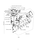
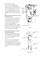
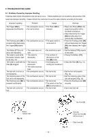
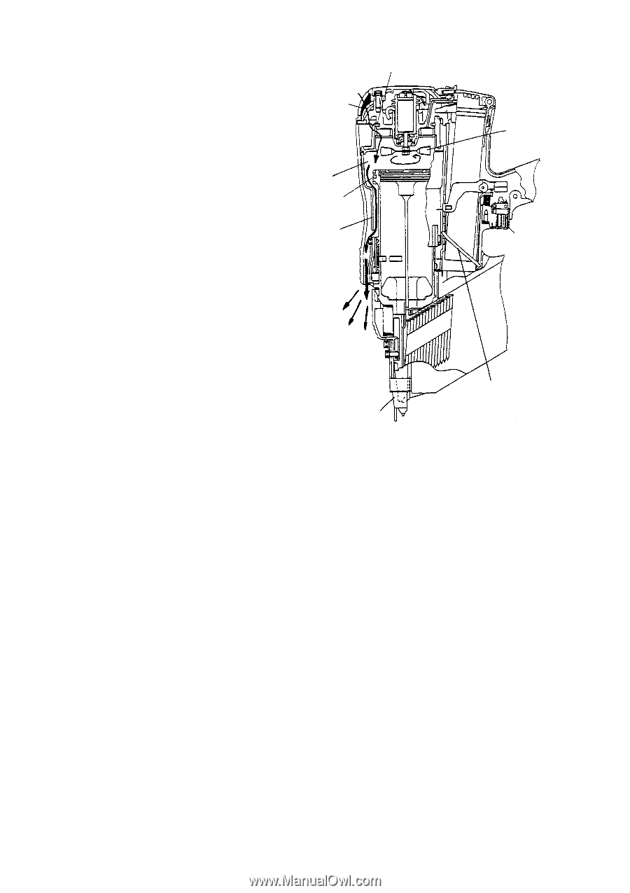
(4) Discharging and cooling When the Trigger [98] is released, the Chamber Lock Bar [100] is returned from the position under the Chamber [24] to the original Filter [4] position. Thus the Chamber [24] and the Pushing Lever [64] are placed in the initial state and sealing by the O-rings [15] and [36] Combustion chamber is released. When the Fan [20] rotates, air passes through the Filter [4], enters the combustion chamber and goes to the outside O-ring [36] Chamber [24] in order to discharge gas and cool the combustion chamber (Fig. 8). O-ring [15] Fan [20] Trigger [98] Pushing Lever [64] Chamber Lock Bar [100] Fig. 8 --- 14 ---
-
 1
1 -
2
-
3
-
4
-
5
-
6
-
7
-
8
-
9
-
10
-
11
-
 12
12 -
 13
13 -
 14
14 -
 15
15 -
 16
16 -
 17
17 -
 18
18 -
 19
19 -
 20
20 -
 21
21 -
 22
22 -
23
-
24
-
25
-
26
-
27
-
28
-
29
-
30
-
31
-
32
-
33
-
34
-
35
-
36
-
37
-
38
-
39
-
40
-
41
-
42
-
43
-
44
-
45
-
46
-
47
-
48
-
49
-
50
-
51
-
52
-
53
-
54
-
55
-
56
-
57
-
58
-
59
-
60
-
61
-
62
-
63
-
64
-
65
-
66
-
67
-
68
-
69
-
70
-
71
-
72
-
73
-
74
-
75
-
76
-
77
-
78
 |
 |
--- 14 ---
O-ring
[15]
Chamber Lock Bar
[100]
Chamber
[24]
Fan
[20]
Pushing Lever
[64]
Fig. 8
(4) Discharging and cooling
When the Trigger
[98]
is released, the
Chamber Lock Bar
[100]
is returned from the
position under the Chamber
[24]
to the original
position.
Thus the Chamber
[24]
and the
Pushing Lever
[64]
are placed in the initial
state and sealing by the O-rings
[15]
and
[36]
is released.
When the Fan
[20]
rotates, air
passes through the Filter
[4]
, enters the
combustion chamber and goes to the outside
in order to discharge gas and cool the
combustion chamber (Fig. 8).
Filter
[4]
Combustion
chamber
O-ring
[36]
Trigger
[98]