Hitachi NR90GC Service Manual - Page 42
Disassembly and Reassembly of Housing Remove the Hex. Socket Hd. Bolt M5 x 50
 |
UPC - 717709008533
View all Hitachi NR90GC manuals
Add to My Manuals
Save this manual to your list of manuals |
Page 42 highlights
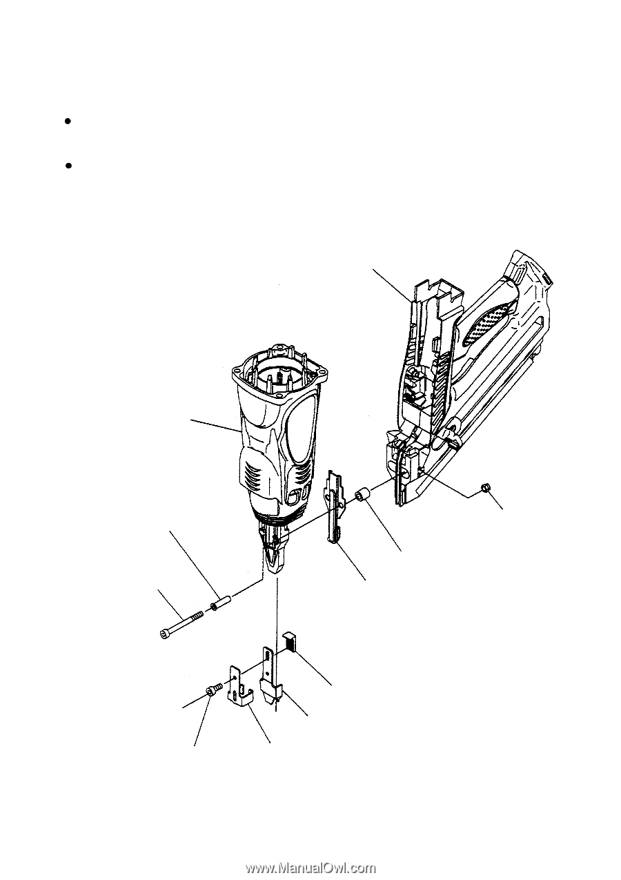
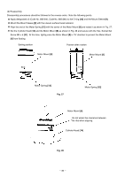
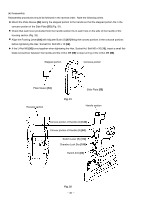
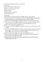
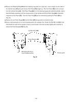
10-4. Disassembly and Reassembly of Housing Section (1) Disassembly and reassembly of housing section, handle section and pushing lever (Fig. 30) [Tools required] Hex. bar wrench (4 mm) (a) Disassembly Remove the cylinder head section from the main body according to 10-2 and 10-3. Remove the Hex. Socket Hd. Bolt M5 x 50 [51] and pull out the Nose Sleeve [52]. Then the output section and the Plate Sleeve [54] can be removed from the main body. Remove the Hex. Socket Hd. Bolt M5 x 10 [66]. Then the Pushing Lever [64], Pushing Stopper [65], Adjuster Bush (S) [67], Blade Guide [53] and U-Nut M5 [56] can be removed. Handle section Housing section Nose Sleeve [52] Hex. Socket Hd. Bolt M5 x 50 [51] U-Nut M5 [56] Plate Sleeve [54] Blade Guide [53] Hex. Socket Hd. Bolt M5 x 10 [66] Adjuster Bush (S) [67] Pushing Lever [64] Pushing Stopper [65] Fig. 30 --- 39 ---
-
 1
1 -
2
-
3
-
4
-
5
-
6
-
7
-
8
-
9
-
10
-
11
-
12
-
13
-
14
-
15
-
16
-
17
-
18
-
19
-
20
-
21
-
22
-
23
-
24
-
25
-
26
-
27
-
28
-
29
-
30
-
31
-
32
-
33
-
34
-
35
-
36
-
 37
37 -
 38
38 -
 39
39 -
 40
40 -
 41
41 -
 42
42 -
 43
43 -
 44
44 -
 45
45 -
 46
46 -
 47
47 -
48
-
49
-
50
-
51
-
52
-
53
-
54
-
55
-
56
-
57
-
58
-
59
-
60
-
61
-
62
-
63
-
64
-
65
-
66
-
67
-
68
-
69
-
70
-
71
-
72
-
73
-
74
-
75
-
76
-
77
-
78
 |
 |