Hitachi NT65MA3 Instruction Manual
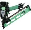
Hitachi NT65MA3 - 2-1/2 Angled Finish Nailer Manual
 |
UPC - 717709011281
View all Hitachi NT65MA3 manuals
Add to My Manuals
Save this manual to your list of manuals |
Hitachi NT65MA3 manual content summary:
- Hitachi NT65MA3 | Instruction Manual - Page 1
MODEL NT 65MA3 Hitachi Power Tools FINISH NAILER NT 65MA3 TECHNICAL DATA AND SERVICE MANUAL N LIST No. E036 Sep. 2006 SPECIFICATIONS AND PARTS ARE SUBJECT TO CHANGE FOR IMPROVEMENT - Hitachi NT65MA3 | Instruction Manual - Page 2
REMARK: Throughout this TECHNICAL DATA AND SERVICE MANUAL, a symbol(s) is(are) used in the place of company name(s) and model name(s) of our competitor(s). The symbol(s) utilized here is(are) as follows: Symbols - Hitachi NT65MA3 | Instruction Manual - Page 3
IN SALES PROMOTION 7 7-1. Instruction Manual ...7 7-2. Warning Label ...7 7-3. Related Laws and Regulations ...8 8. MECHANISM AND OPERATION PRINCIPLE 8 8-1. Mechanism ...8 8-2. Interchangeability ...10 8-3. Operation Principle ...11 9. TROUBLESHOOTING GUIDE ...14 9-1. Troubleshooting and - Hitachi NT65MA3 | Instruction Manual - Page 4
1. PRODUCT NAME Hitachi 2-1/2" Finish Nailer, Model NT 65MA3 2. MARKETING OBJECTIVE The new Model NT 65MA3 finish nailer is a minor-changed version of the current Model adjusting mechanism Easy-to-use clogged nail release mechanism "Single actuation/contact actuation" selector --- 1 --- - Hitachi NT65MA3 | Instruction Manual - Page 5
(Gauge pressure) 3 pcs./sec 1.9 kg (4.2 lbs.) Dimensions 343 mm x 305 mm x 76 mm (Length x Height x Width) (13-1/2" x 12" x 3") Nail feed system Nail capacity Spiral spring 100 nails Air consumption Air inlet Packaging 1.20 ltr/cycle at 6.9 bar (1.20 ltr/cycle at 7 kgf/cm2) (.042 ft3/cycle at - Hitachi NT65MA3 | Instruction Manual - Page 6
the work to be performed. A FULL SEQUENTIAL ACTUATION MECHANISM KIT (SEQUENTIAL TRIP MECHANISM KIT) is also available as an option. Each nailing operation is as follows. SINGLE ACTUATION MECHANISM (SINGLE SEQUENTIAL ACTUATION MECHANISM): First, press the pushing lever against the wood; next, pull - Hitachi NT65MA3 | Instruction Manual - Page 7
NT 65MA3 utilizes small-head, T-shaped nails (finish nails) collated by tapes. Applicable nails are shown below. CAUTION: Ensure that nails are as specified in Fig. 1. Other nails will cause clogging of nails and subsequent damage to the nailer. 15-gauge finish nail (collating angle 34û) Min. Max - Hitachi NT65MA3 | Instruction Manual - Page 8
nailing energy Nailer output energy Plywood (12 mm (.472") thick) x 6 P S NT 65MA NT 65MA2 NT 65MA3 NT65MA3 Fig. 3 Required nailing energy and nailer who want to use it. Salespersons must instruct the customers to read the Handling Instructions attached to the full sequential actuation mechanism - Hitachi NT65MA3 | Instruction Manual - Page 9
6. COMPARISONS WITH SIMILAR PRODUCTS Maker Model name Operating pressure HITACHI NT 65MA3 NT 65MA2 4.9 to 8.3 bar (5 to 8.5 kgf/cm2 ) (70 to 120 type Angle: 34û Blow nozzle Provided None None None None Nailing operation switching device Provided None None None None Direction change - Hitachi NT65MA3 | Instruction Manual - Page 10
most efficient use of the Model NT 65MA3 Nailer by all of our customers, it is very important that at the time of sale the salesperson carefully ensures that the buyer seriously recognizes the importance of the contents of the Instruction Manual, and fully understands the meaning of the precautions - Hitachi NT65MA3 | Instruction Manual - Page 11
nails and staples, there is an ever-present danger of misfiring and subsequent possible serious injury. Accordingly, close attention in handling is absolutely necessary at all times. Carefully ensure that the customer is fully aware of the precautions listed in the Instruction Manual Following parts - Hitachi NT65MA3 | Instruction Manual - Page 12
[33] Blade Guide [37] Pushing Lever (A) [40] Blow nozzle section Knob [24] Cap (A) [49] Body Ass'y [30] Control valve section Air Plug NPT 1/4 [51] Trigger (A) [53] Magazine Cover [76] Nail Stopper [81] Nail Rail [79] Magazine [82] Nail Feeder (B) [80] Magazine section Nail Feeder (A) [74 - Hitachi NT65MA3 | Instruction Manual - Page 13
that are interchangeable though their code numbers are different are described in detail. Parts that are not interchangeable with those of the Model NT 65MA2 Parts Top Cover [3] NT 65MA3 Newly designed NT 65MA2 Exhaust Cover [5] Newly designed Gasket [6] Newly designed Body Ass'y [30] Newly - Hitachi NT65MA3 | Instruction Manual - Page 14
into the Cylinder Plunger (A) [68] Exhaust valve Valve Piston (B) [65] Valve piston lower chamber [11], forcing the Piston [15] downward to strike the nail. When the Piston [15] passes the cylinder hole, Fig. 6 Control valve section the compressed air flows into the return air chamber and is - Hitachi NT65MA3 | Instruction Manual - Page 15
(3) During return: (Fig. 7 and Fig. 8) Exhaust Cover [5] 1) When either Pushing Lever (A) [40] or Trigger (A) Exhaust vent Head valve chamber [53] is released, Plunger (A) [68] goes down and the Head compressed air in the accumulator flows into the Valve (A) [10] valve piston lower chamber. 2) - Hitachi NT65MA3 | Instruction Manual - Page 16
53] is held, Plunger (A) [68] returns (lowers) completely as shown in Fig. 10. Thus the Piston [15] returns (raises) fully. Accordingly, continuous nailing can be accomplished by pushing only Pushing Lever Valve piston lower chamber Pushing Lever (B) [36] Switching device (Change Knob [57]) (upward - Hitachi NT65MA3 | Instruction Manual - Page 17
9. TROUBLESHOOTING GUIDE 9-1. Troubleshooting and Correction Problem 1) Nails cannot be driven. Possible cause ( : most-common cause) Magazine is not loaded with specified genuine nails. Magazine is loaded with abnormal nails (bent nails, abnormal collation, others). Nail - Hitachi NT65MA3 | Instruction Manual - Page 18
Problem 1) Nails cannot be driven. (continued) Possible cause ( : Nailer cannot be used because the material is beyond its applicable range. Replace the part. Regrind (see 9-2, "Regrinding the Driver Blade"). Replace the O-ring. Replace the part. Replace the part. Apply grease. Use specified nails - Hitachi NT65MA3 | Instruction Manual - Page 19
Problem Possible cause ( : most-common cause) 4) Nails jam. (continued ring of plunger (A) and valve piston (B). Check each part for abnormalities (worn, damaged, deformed, etc.) The position heated. Excessive grinding will rapidly reduce the service life of the driver blade. In such a case, replace the - Hitachi NT65MA3 | Instruction Manual - Page 20
Correction of Air Leakage Air leakage repair location Repair procedure (1) Check the points of the following parts marked by an asterisk for abnormal condition. (2) Next, check the seal parts (marked with a double circle) for wear, flaws and damage. (3) And then, check other places. Air leakage - Hitachi NT65MA3 | Instruction Manual - Page 21
Air leakage point (C) Blade guide (D) Air outlet, valve bushing Possible cause With control valve OFF With control valve ON The Cylinder O-Ring (I.D 63.1) [12] is abnormal (broken or damaged). The - Hitachi NT65MA3 | Instruction Manual - Page 22
[Bold] numbers in the descriptions below correspond to the item numbers in the Parts List and exploded assembly diagram. CAUTION: Before disassembly or reassembly, be sure to disconnect the air hose from the nailer (with your finger released from the trigger) to exhaust all the compressed air and - Hitachi NT65MA3 | Instruction Manual - Page 23
10-2. Disassembly and Reassembly of the Output Section (1) Disassembly and reassembly of the Exhaust Cover [5], Head Valve (A) [10], Cylinder [11], Piston [15], Piston Bumper [25], etc. (See Fig. 12.) Hex. Socket Hd. Bolt M6 x 12 [1] Plate [2] Top Cover [3] Hex. Socket Hd. Bolt (W/Sp. Washer) M5 x - Hitachi NT65MA3 | Instruction Manual - Page 24
Groove of the Exhaust Cover [5] O-ring (I.D 20.8) [9] Exhaust Cover [5] Head Valve (A) [10] Fig.13 (b) Reassembly Disassembly procedures should be followed in the reverse order. Note the following points: Apply grease to the inside of the Cylinder [11], O-ring (I.D 34.7) [14] and the Cylinder - Hitachi NT65MA3 | Instruction Manual - Page 25
Ball D3.97 [55] Spring (C) [56] Carefully disassemble so as not to lose these parts. Valve Bushing (B) [61] O-ring (S-18) [62] O-ring (I.D 8.8) [63] (A) [53] together with the driving section (Pushing Lever (B) [36], Blade Guide [37], etc.), remove Trigger (A) [53] while forcing down Plunger (A) [ - Hitachi NT65MA3 | Instruction Manual - Page 26
the upper side of the Body Ass'y [30] and push the top of Valve Valve Piston (B) [65] Valve Bushing (A) [70] Piston (B) [65]. Now, the parts forming the control valve can be taken out except Valve Bushing (A) [70] and the Head Valve O-Ring Plunger (A) [68] When disassembling, do not pull out - Hitachi NT65MA3 | Instruction Manual - Page 27
(b) Reassembly Disassembly procedures should be followed in the reverse order. Note the following points: Be extremely careful to prevent the entry of foreign particles into the control valve section. Thoroughly apply grease to the O-ring (I.D 1.8) [69] on Plunger (A) [68], O-ring (S-4) [64], O-ring - Hitachi NT65MA3 | Instruction Manual - Page 28
nail is raised when Lock Lever [34] adjusting the driving depth (refer to ADJUSTING THE NAILING DEPTH on page 21 in the Instruction Manual) 30 [32] with the hex. bar wrench (5 mm). Now, the Blade Guide [37], Guide Plates (A) [33] and (B) Fig. 20 Disassembly and reassembly of the driving - Hitachi NT65MA3 | Instruction Manual - Page 29
procedures should be followed in the reverse order and tighten the two Hex. Socket Hd. Bolts M6 x 30 [32] after making the Blade Guide [37], Guide Plates (A) [33] and (B) [31] flush with the Body Ass'y [30]. After assembly, check that Pushing Levers (A) [40], (B) [36] and the Adjuster [38] move - Hitachi NT65MA3 | Instruction Manual - Page 30
tightened while pressing the Magazine [82] and the Magazine Cover [76] so that there will be no space between the Magazine [82] and the Blade Guide [37]. Lubricate the Nail Rail [79] and the Ribbon Spring [72] with Hitachi pneumatic tool lubricant to smooth the movement of - Hitachi NT65MA3 | Instruction Manual - Page 31
no air leakage and the Model NT 65MA3 does not operate (i.e., check that the Piston [15] does not come out of the Blade Guide [37] tip (outlet of nails) when it is left for five seconds or more). (3) Set the Change Knob [57] to "contact actuation" (see 5-2). Check the following when the - Hitachi NT65MA3 | Instruction Manual - Page 32
Knob Plunger O-ring x 3 Valve Bushing Top Cover Exhaust Cover Guide Plate (B) Gasket Guide Plate (A) Head Valve Spring Blade Guide O-ring Magazine Head Valve (A) Magazine Cover Nail Feeder (A) Nail Rail Nail Feeder (B) Pushing Lever Cylinder (B) Cylinder O-ring Holder Spring O-ring - Hitachi NT65MA3 | Instruction Manual - Page 33
Hitachi Power Tools LIST NO. E036 PNEUMATIC TOOL PARTS LIST FINISH NAILER Model NT 65MA3 2006 • 9 • 12 (E1) 24 501 1 23 22 2 21 3 20 19 51 502 18 50 4 17 49 16 48 503 47 5 504 25 - Hitachi NT65MA3 | Instruction Manual - Page 34
1 30 885-963 BODY ASS'Y 1 INCLUD. 46 31 881-764 GUIDE PLATE (B) 1 32 949-661 HEX. SOCKET HD. BOLT M6X30 (10 PCS.) 2 33 881-743 GUIDE PLATE (A) 1 34 884-323 LOCK LEVER 1 35 877-894 HOLDER . BOLT M5X16 (10 PCS.) 3 51 AIR PLUG NPT 1/4 1 --- 2 --- * ALTERNATIVE PARTS NT 65MA3 9 -- 06 - Hitachi NT65MA3 | Instruction Manual - Page 35
PARTS ITEM NO. CODE NO. 52 DESCRIPTION HITACHI LABEL NO. USED 1 53 884-145 TRIGGER (A) 1 54 949-865 ROLL PIN D3X28 (10 PCS.) 3 55 959-155 STEEL BALL D3.97 (10 PCS.) 1 56 982-454 SPRING (C) 1 57 884-335 CHANGE KNOB 1 58 884-336 PUSHING LEVER GUIDE 1 74 881-746 NAIL FEEDER (A) 1 75 - Hitachi NT65MA3 | Instruction Manual - Page 36
PLUNGER (B) 1 604 878-888 O-RING (I.D 1.8) 1 605 880-672 VALVE PISTON (B) 1 606 884-322 TRIGGER PIN 1 607 881-768 GRIP TAPE (A) 1 608 880-407 TAPE 2 --- 4 --- * ALTERNATIVE PARTS Printed in Japan 9 -- 06 (060912N) - Hitachi NT65MA3 | Instruction Manual - Page 37
-
 1
1 -
 2
2 -
 3
3 -
 4
4 -
 5
5 -
 6
6 -
 7
7 -
8
-
9
-
10
-
11
-
12
-
13
-
14
-
15
-
16
-
17
-
18
-
19
-
20
-
21
-
22
-
23
-
24
-
25
-
26
-
27
-
28
-
29
-
30
-
31
-
32
-
33
-
34
-
35
-
36
-
37
 |
 |

TECHNICAL
DATA
AND
SERVICE
MANUAL
FINISH
NAILER
NT
65MA3
SPECIFICATIONS
AND
PARTS
ARE
SUBJECT
TO
CHANGE
FOR
IMPROVEMENT
LIST No. E036
Sep. 2006
N
MODEL
NT
65MA3
Hitachi
±
Power Tools