Hitachi NT65MA3 Instruction Manual - Page 24
and the Retaining Ring E-type for D4 Shaft
 |
UPC - 717709011281
View all Hitachi NT65MA3 manuals
Add to My Manuals
Save this manual to your list of manuals |
Page 24 highlights
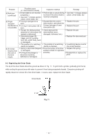
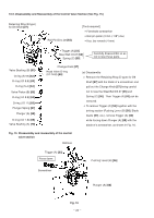
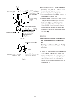
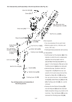
Groove of the Exhaust Cover [5] O-ring (I.D 20.8) [9] Exhaust Cover [5] Head Valve (A) [10] Fig.13 (b) Reassembly Disassembly procedures should be followed in the reverse order. Note the following points: Apply grease to the inside of the Cylinder [11], O-ring (I.D 34.7) [14] and the Cylinder O-ring (I.D 63.1) [12] before reassembly. Apply grease to the sliding surface a of the Exhaust Cover [5] and Head Valve (A) [10] and charge about 0.5 g (.018 oz) of grease in the groove of the Exhaust Cover [5] (Fig. 13). Apply grease to the lip portions b and c of Head Valve (A) [10] (Fig. 13). Apply grease to the O-ring (I.D 20.8) [9]. Mount the O-ring (I.D 20.8) [9] to Head Valve (A) [10], then mount it to the Exhaust Cover [5]. (2) Disassembly and reassembly of the Valve Bushing [22], Plunger [18], etc. (See Fig. 14.) [Tools required] Socket wrench (14 mm) Flat-blade head screwdriver (a) Disassembly Remove the Valve Bushing [22] with a socket wrench (14 mm ). The Valve Packing [16] and the Spring [17] can now be removed. Remove the Knob [24] and the Retaining Ring (E-type) for D4 Shaft [23] then the Plunger [18] can be removed from the Valve Bushing [22]. (a) Reassembly Disassembly procedures should be followed in the reverse order. Note the following points: Apply grease to the O-ring (1AP-3) [19], O-ring (S3) [20] and the O-ring (S-10) [21]. Mount the Retaining Ring (E-type) for D4 Shaft [23] to the Plunger [18] then press the Knob [24] against the Retaining Ring (E-type) for D4 Shaft [23] to mount it. O-Ring (S-10) [21] O-Ring (S3) [20] O-Ring (1AP-3) [19] Knob [24] Retaining Ring (E-type) for D4 Shaft [23] Exhaust Cover [5] Valve Bushing [22] Plunger [18] Spring [17] Valve Packing [16] Fig. 14 Disassembly and reassembly of the valve bushing, plunger, etc. --- 21 ---
-
 1
1 -
2
-
3
-
4
-
5
-
6
-
7
-
8
-
9
-
10
-
11
-
12
-
13
-
14
-
15
-
16
-
17
-
18
-
 19
19 -
 20
20 -
 21
21 -
 22
22 -
 23
23 -
 24
24 -
 25
25 -
 26
26 -
 27
27 -
 28
28 -
 29
29 -
30
-
31
-
32
-
33
-
34
-
35
-
36
-
37
 |
 |
