Hitachi NT65MA3 Instruction Manual - Page 14
Operation Principle, As a result, the Head Valve Spring
 |
UPC - 717709011281
View all Hitachi NT65MA3 manuals
Add to My Manuals
Save this manual to your list of manuals |
Page 14 highlights
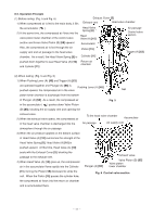
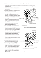
8-3. Operation Principle (1) Before nailing: (Fig. 5 and Fig. 6) 1) When compressed air is fed to the main body, it fills Exhaust Cover [5] Exhaust vent Head valve chamber the accumulator ( ). Head Valve Spring [8] 2) At the same time, the compressed air flows into the valve piston lower chamber of the control valve Head Valve (A) [10] Air passage Control valve section section and forces Valve Piston (B) [65] upward. Also, the compressed air is fed through the air supply vent and air passage to the head valve chamber. As a result, the Head Valve Spring [8] is Accumulator Piston [15] Cylinder [11] Trigger (A) [53] pushed down together to seal Head Valve (A) [10] Return air chamber and Cylinder [11]. (2) When nailing: (Fig. 5 and Fig. 6) 1) When Pushing Lever (A) [40] and Trigger (A) [53] are operated together and Plunger (A) [68] is Pushing Lever (A) [40] pushed upward, the compressed air in the valve Nail piston lower chamber is discharged from the bottom of Plunger (A) [68]. As a result, the compressed air Fig. 5 in the accumulator ( ) pushes down Valve Piston (B) [65], blocking the air supply vent and opening the exhaust valve. 2) When the exhaust valve opens, the compressed air in the head valve chamber is discharged into the To the head valve chamber Accumulator Air passage Air supply vent atmosphere through the air passage. 3) When the air pressure applied on the bottom surface of Head Valve (A) [10] overcomes the strength of the Head Valve Spring [8], Head Valve (A) [10] is pushed upward. At this time, Head Valve (A) [10] seals with the Exhaust Cover [5], blocking the passage to the exhaust vent. 4) When Head Valve (A) [10] goes up, the compressed air in the accumulator flows rapidly into the Cylinder Plunger (A) [68] Exhaust valve Valve Piston (B) [65] Valve piston lower chamber [11], forcing the Piston [15] downward to strike the nail. When the Piston [15] passes the cylinder hole, Fig. 6 Control valve section the compressed air flows into the return air chamber and is accumulated there. --- 11 ---
-
 1
1 -
2
-
3
-
4
-
5
-
6
-
7
-
8
-
 9
9 -
 10
10 -
 11
11 -
 12
12 -
 13
13 -
 14
14 -
 15
15 -
 16
16 -
 17
17 -
 18
18 -
 19
19 -
20
-
21
-
22
-
23
-
24
-
25
-
26
-
27
-
28
-
29
-
30
-
31
-
32
-
33
-
34
-
35
-
36
-
37
 |
 |
