Hitachi W6VM Instruction Manual - Page 11
Confirm the direction of bit rotation, Fig. 2, Adjusting the tightening depth, Fig. 3
 |
UPC - 717709008748
View all Hitachi W6VM manuals
Add to My Manuals
Save this manual to your list of manuals |
Page 11 highlights
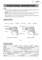
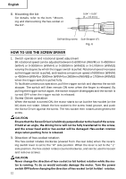
English 6. Confirm the direction of bit rotation (Fig. 2) The bit rotates clockwise (viewed from the rear side) when the reversing switch lever is set to the "R" side position. When the lever is set to the "L" side position, the bit rotates counterclockwise and can be used to loosen and remove screws. CAUTION: Never change the bit rotating direction while operating the Screw Driver. Turn the main switch off before changing the rotating direction, otherwise, burning of the motor will result. 7. Adjusting the tightening depth (Fig. 3) The tightening depth can be adjusted by turning locator right and left with click feeling. (1) For hex-head screws (Fig. 4) Mount a hex-head screw on the hexsocket and set the distance between the sub-stopper end and the screw head neck to 0.04" - 0.06" (1 - 1.5 mm). (2) For drywall screws (Fig. 5) Mount a drywall screw on the bit, and set the distance between the sub-stopper end and the screw head to 0.06" - 0.07" (1.5 - 2 mm). (3) For cross-recessed self-drilling screws (Fig. 6) Mount a self-drilling screw on the bit, and set the distance between the substopper end and the screw head bottom to 0.04" - 0.06" (1 - 1.5 mm). R side Lever Fig. 2 Sub Locator Stopper (B) Gear cover Fig. 3 0.04" - 0.06" (1 - 1.5 mm) Hex. head Sub-Stopper (B) screw Fig. 4 0.06" - 0.07" (1.5 - 2 mm) Drywall screw Sub-Stopper (F) Fig. 5 11
-
 1
1 -
2
-
3
-
4
-
5
-
 6
6 -
 7
7 -
 8
8 -
 9
9 -
 10
10 -
 11
11 -
 12
12 -
 13
13 -
 14
14 -
 15
15 -
 16
16 -
17
-
18
-
19
-
20
-
21
-
22
-
23
-
24
-
25
-
26
-
27
-
28
-
29
-
30
-
31
-
32
-
33
-
34
-
35
-
36
-
37
-
38
-
39
-
40
-
41
-
42
-
43
-
44
-
45
-
46
-
47
-
48
-
49
-
50
-
51
-
52
-
53
-
54
-
55
-
56
 |
 |
