Honeywell 5804 Installation Guide - Page 2
ÊN7674-6V2LŠ - case
 |
UPC - 781410005129
View all Honeywell 5804 manuals
Add to My Manuals
Save this manual to your list of manuals |
Page 2 highlights
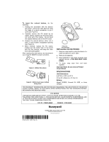
To insert the colored buttons, do the following: 1. Holding the transmitter with the buttons face down, remove the case back by using the blade of a small screwdriver to pry it open (see Figure 2). 2. Carefully remove the PC board by its rubber casing, making sure the board does not come out of the casing. Do not bend the exposed battery tabs on the PC board. 3. Replace the desired buttons, either red or blue, in each button's designated opening (see Figure 3). 4. When finished, replace the PC board, making sure the button tabs on the board face the four buttons, and snap the case front and back together. After inserting the new buttons, we recommend you check the 5804E for proper operation. Figure 2: Battery tabs shown Blue Red Figure 3: 5804E shown open, buttons facing down 5804E-003-V0 5804E-002-V0 + POS. end must face down + POS. end must face down REPLACING THE BATTERIES 1. Remove case back by using the blade of a small screwdriver to pry it open. 2. Remove old batteries. 3. Place batteries in case back locations (see diagram above). + POS END MUST FACE DOWN. 4. To close, snap case front and back together. Important Note: Do not remove Printed Circuit Board. SPECIFICATIONS Unit Dimensions: 2.25" W x 1.50"H x 0.5" D 57mm W x 38mm H x 12.7mm D Battery: Maxell CR2025, Duracell DL 2025, or Varta CR2025 5804E-004-V0 FOR WARRANTY INFORMATION AND FOR DETAILS REGARDING THE LIMITATIONS OF THE ENTIRE ALARM SYSTEM, REFER TO THE INSTALLATION INSTRUCTIONS FOR THE RECEIVER/CONTROL WITH WHICH THIS DEVICE IS USED. FCC NOTICE THIS DEVICE COMPLIES WITH PART 15 OF FCC RULES. OPERATION IS SUBJECT TO THE FOLLOWING TWO CONDITIONS: (1) THIS DEVICE MAY NOT CAUSE HARMFUL INTERFERENCE, AND (2) THIS DEVICE MUST ACCEPT ANY INTERFERENCE RECEIVED, INCLUDING INTERFERENCE THAT MAY CAUSE UNDESIRED OPERATION. FCC ID: CFS8DL5804E CANADA: 573F-5804E ÊN7674-6V2LŠ N7674-6V2 10/04 Rev. A
-
 1
1 -
 2
2
 |
 |
