Honeywell 6149EX Installation Guide
Honeywell 6149EX Manual
 |
View all Honeywell 6149EX manuals
Add to My Manuals
Save this manual to your list of manuals |
Honeywell 6149EX manual content summary:
- Honeywell 6149EX | Installation Guide - Page 1
K6205EXV3 5/07 Rev. B ADEMCO 6149EX & 6165EX Remote Keypads INSTALLATION AND SETUP GUIDE GENERAL INFORMATION The ADEMCO 6149EX and ADEMCO 6165EX are addressable remote keypads designed for use with ADEMCO control panels. The keypads have the following features: • Built-in Piezo • Special Function - Honeywell 6149EX | Installation Guide - Page 2
INSTRUCTIONS FOR THE CONTROL PANEL WITH WHICH THIS DEVICE IS USED FOR WARRANTY INFORMATION AND LIMITATIONS OF THE ENTIRE ALARM SYSTEM. To obtain applicable EU compliance Declaration of Conformities for this product, please refer to our Website http://www.security.honeywell.com/hsce/international
-
 1
1 -
 2
2
 |
 |
K6205EXV3
5/07
Rev. B
ADEMCO 6149EX & 6165EX
ADEMCO 6149EX & 6165EX
ADEMCO 6149EX & 6165EX
ADEMCO 6149EX & 6165EX
Remote Keypads
Remote Keypads
Remote Keypads
Remote Keypads
INSTALLATION AND SETUP GUIDE
GENERAL INFORMATION
The ADEMCO 6149EX and ADEMCO 6165EX are
addressable remote keypads designed for use with ADEMCO
control panels. The keypads have the following features:
•
Built-in Piezo
•
Special Function Keys
Addresses are set via the keypad keys, which are continuously
backlit for convenience.
KEYPAD DISPLAYS AND LEDS
The keypads have the following display features:
Model
Fixed
Word
Display
2-line
Alpha
Display
2-digit
Zone
Identifier
Custom
Zone
Descriptors
Backlit
Display
6149EX
✓
✓
6165EX
✓
✓
✓
✓
*
*
Permanent display backlighting is an option on some control panels
(refer to the Control's Installation and Setup Guide for details).
The following table shows the LEDs and their functions:
LED
Function
ARMED (Red)
Lights when the system is armed in any mode
READY (Green)
Lights when the system is “ready” to be armed.
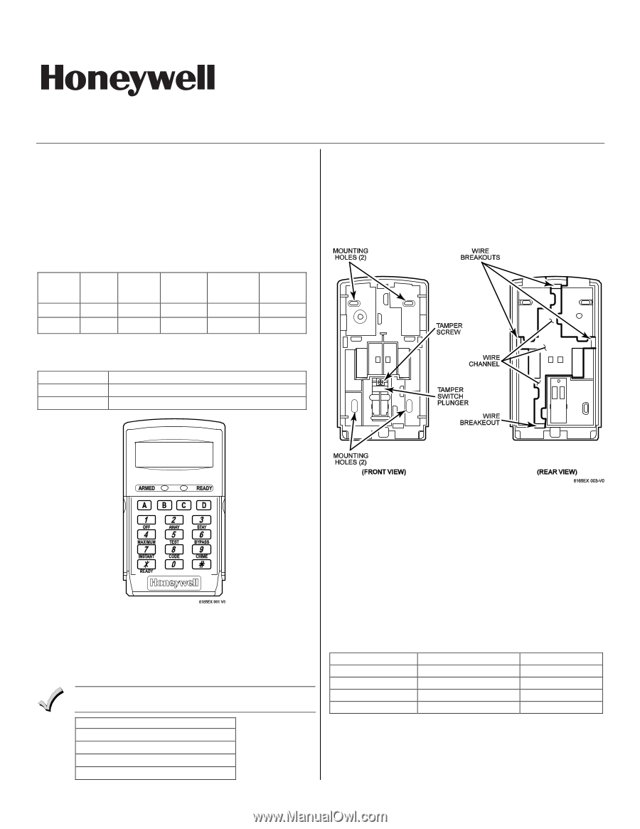
Figure 1 – 6149EX/6165EX Keypad
(shown with cover removed)
SPECIAL FUNCTION KEYS
The keypads also feature function keys.
These keys may be
programmed for panic alarms or other special functions such
as macros. See the control's instructions for details.
Function keys must be held down for at least two (2) seconds
to activate an alarm. Key pairs activate immediately.
Special Function Keys
A or [1] and [
✻
]
B or [
✻
] and [#]
C or [3] and [#]
D
MOUNTING AND WIRING THE KEYPAD
The keypad must be mounted within the protected premises.
It can be surface mounted directly to walls. A built-in tamper
switch detects separation of the case-back from its mounting
surface. To include tamper protection, a tamper screw must be
inserted in the case-back, as shown in Figure 2.
NOTE:
Not all control panels support keypad tamper reporting. Refer to
the individual Control Panel’s Installation and Setup Guide.
Figure 2 – Mounting the keypad
1.
Separate the case back from the keypad.
2.
If using the tamper switch place the case back on a flat
surface and insert a screw through the tamper switch
plunger in the case back, as shown in Figure 2. Tighten
the tamper screw until the upper portion of the tab (near
the tamper screw) contacts the case back.
3.
Route wiring from the control panel through the opening
in the case back.
4.
Mount the case back to a wall.
5.
Wire directly from the keypad’s terminal block
to the
terminal block on the control board as follows:
Wiring Table (All Keypads)
Keypad
Control Panel
Wire Color
G
▲
Data In
Green
−
−
Aux Pwr (GND)
Black
+
+ Aux Pwr
Red
▼
Y
Data Out
Yellow
Refer to the control panel’s Installation and Setup Guide for
more complete details.
6.
Reattach the keypad
to its case back.