Honeywell HP300ULX Installation Instructions - Page 1
Honeywell HP300ULX Manual
 |
View all Honeywell HP300ULX manuals
Add to My Manuals
Save this manual to your list of manuals |
Page 1 highlights
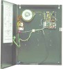
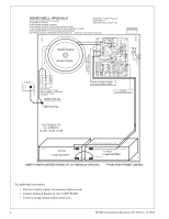
Honeywell 12 Clintonville Road Northford, CT 06472 http://www.honeywellpower.com HP300ULX Access Control Power Supply/Charger PN 52386:A 12/29/05 ECN 04-350 Product Installation Document This product follows under the UL1481 Fire Alarm Systems, UL603 Burglary Alarm Systems and UL294 Access Control Systems. The HP300ULX unit is to be installed in a fail safe mode unless authorized by the local AHJ. This product must be installed in compliance with Article 760 of the National Electrical Code, NFPA70, as well as NFPA72 National Fire Alarm Code and all applicable local codes. 1 Description The HP300ULX is a 12VDC or 24VDC power supply with AC fail and Battery fail supervision. The unit has not been evaluated as elevator equipment, and is not authorized for bell output in Mercantile applications. 2 Specifications 1. Input voltage: 120VAC 60Hz; Current: 1.50A max. 2. Output Voltage: 12VDC or 24VDC, jumper selectable; Current: 2.5A continuous output maximum, 2.0A plus battery charger (not supervised). 3. Fail safe dry contact output on AC Failure (within one minute). 4. Built-in charger for sealed lead acid or gel cell type batteries. 5. Instantaneous transfer to stand-by battery on AC failure. 6. Battery presence detection (within 1 minute) 7. Battery low disconnect at 9.90VDC or 19.90VDC. 8. High voltage disconnect at 15VDC or 30VDC. 9. Yellow LED (L3) indication for battery disconnected and battery low. 10. Fail safe dry contact output for Battery trouble (Fail Safe). 11. Battery polarity reversal protection. 12. Thermal overload and short circuit protection. 13. DC output PTC activated indication by Red LED (L2). 14. DC output failure indication by Red LED ( L4 ). 15. AC presence indication by Green LED ( L1 ). 16. DC output indication by Red LED ( L5 ). 17. Battery Leads included. 18. Power Board Dimensions: 5"L x 3.9"W x 1.5"H. 19. Enclosure Dimension: 17"L x 13.5"W x 4.75"H. Accommodates two 12 Volt 12AH batteries. When using larger batteries, a UL approved enclosure must be used. 3 Installation Instructions 1. Mounting The power supply should be installed in accordance with all Governing National Electrical and Local Codes. Mount the power supply securely in the desired location using the four (4) mounting holes. 2. Power Supply Input Connection Continued on next page...
-
 1
1 -
 2
2 -
 3
3 -
 4
4
 |
 |
