Honeywell HP300ULX Installation Instructions - Page 2
Maintenance, Warranty, Output Connections, Alarm/Trouble Output, Power Up - notifier
 |
View all Honeywell HP300ULX manuals
Add to My Manuals
Save this manual to your list of manuals |
Page 2 highlights
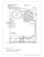
Before connecting power, review the entire wiring diagram for correct installation (see Fig. 1). With the AC power disconnected, connect 120VAC to the Fuse Block as follows; L=Black (HOT), N=WHITE (Neutral), G=GREEN (Ground). Select the output voltage 12VDC or 24VDC using Jumper J1 of the Power Board J1 OFF=12VDC, J1 ON=24VDC. Voltage is Factory set and Re-Adjusting will void Warranty. 3. Output Connections Connect the load to the DC (+) and DC (-) terminals observing polarity. 4. Alarm/Trouble Output a.) AC Fail: Connect the "AC Fail" output "Form C" dry contacts to the monitoring device. In case of AC loss the relay, which is Fail Safe, will de-energize within one (1) minute. b.) Battery Fail: Connect the Battery Fail output "Form C" dry contacts to the monitoring device. If a Battery is not connected or improperly connected, the Yellow LED (L3) will turn ON within one (1) minute and the Battery Fail output relay, which is Fail Safe, will de-energize. 5. Power Up When all wiring is complete and checked, switch ON the AC Power. The Green Led (L1) will come ON indicating AC presence and the AC relay will be energized. Connect Battery observing the correct polarity. For 24VDC use the battery link provided to connect the two (2) 12 Volt Batteries in series. Secure the enclosure with the 4 screws and with the Key Lock provided. NOTE: For UL603 or UL294 applications use a Tamper Switch (Catalog number HPVM3 available separately), and included enclosure key lock. Connect the tamper switch NC outputs to monitoring device to notify of enclosure tampering. ! WARNING: To reduce risk of electric shock, do not expose unit to rain or excess moisture, and disconnect power before servicing unit. For continuous protection against hazard, replace fuses only with exact type and rating. A readily accessible switched circuit breaker must be available to disconnect main power as required. All power limited wiring should be routed so that it cannot touch non-power limited wiring; minimum spacing 1/4". Installation and servicing should only be made by qualified personnel; contains no user-serviceable parts. Install in accordance with all local regulations and the National Electrical Code. 4 Maintenance This unit should be tested at least once a year to verify correct operation in accordance with the following recommendations; • Output Voltage Test Voltage output should be tested under normal load conditions to verify correct levels. • Battery Test Battery should be checked for full charge under normal load conditions. This check should verify correct voltage at both battery terminals and also at the Battery output point on the board to ensure the integrity of all connecting wiring. Note: It is recommended to replace the battery at least every 4 years. Continued on next page... 2 HP300ULX Installation Document P/N 52386:A 12/29/05
-
 1
1 -
 2
2 -
 3
3 -
 4
4
 |
 |
