Honeywell HTR4 Quick Start Guide - Page 1
Honeywell HTR4 Manual
 |
View all Honeywell HTR4 manuals
Add to My Manuals
Save this manual to your list of manuals |
Page 1 highlights
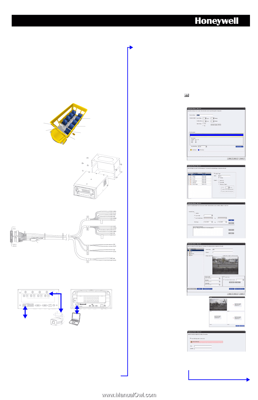
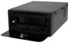
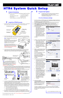
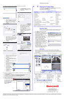
HTR4 System Quick Setup 1 Unpack Everything Make sure you have everything you need before you begin the installation: • HTR4 Recorder • 1 to 4 mobile CCTV cameras • Recorder and camera cables • Administrator CD-ROM disc • Wiring harness • Mounting hardware • Optional installation kits (HTR4GPS, HTRDP, and so on) 3 Program the System Note To ensure that you can read, write, and modify Configuration data files and application support files, Honeywell recommends that all users be administrator group members of the Windows operating system. First Time Mandatory Settings 2 Install the HTR4 Recorder 1. Choose a location and mounting option that provides convenient access, is not subject to high vibration or heat, and cannot be interfered with by unauthorized personnel. Possible Mounting Locations Glove box (inside or underneath) Bulkhead (on front or underneath) ** * Middle of vehicle (underneath seat) * ** Passenger seat (underneath seat) Driver seat (between seat and wall, or underneath) Console 2. Attach the U-shaped bracket to the pre-drilled mounting surface using the sheet metal screws. Secure the recorder to the bracket with the machine screws (hardware included). Note You can mount your recorder in any orientation needed. The U-shaped bracket can be inverted. It can be used to mount the recorder suspended underneath a flat surface or to mount it supported on top of a flat surface. Suspended mount OR Supported mount TIP! For more secure installations, we recommend you install your recorder inside the HTENCLHTR security enclosure. See the HTENCLHTR Security Enclosure Installation Guide for more information. 3. Connect the 24-pin Interface connector of the wiring harness to the recorder. Wire the triggers and alarms to the vehicle electrical system. Connect the power cables to the vehicle battery. Connect the GPS cabling to the HTR4GPS module, if installed. Alarms NO1 NO2 NC1 NC2 COM1 COM2 Power harness: 20, 40 and 60 foot cables Triggers TRIG1 TRIG2 TRIG3 TRIG4 TRIG5 TRIG6 Fuse box (ATO 7.5) Note If you are installing the recorder into a vehicle that previously ran an HTRD400 or HTRD100 recorder, you can purchase a wiring harness adapter that allows you to use your currently wired triggers. See the HTR4 System Reference Guide for more information. Reserved for GPS Power For future use Power for GPS To vehicle battery 4. Install up to four cameras. The primary camera is typically installed at the front interior of the vehicle looking towards the back. Other cameras might be installed on the ceiling halfway down the aisle and on the bulkhead looking towards the driver and/or front door. For more information, refer to the Installation Guide that came with your camera. 5. Connect the camera(s) to the power, audio and video ports on the recorder's rear panel. Rear Panel Front Panel 1 1 2 2 3 3 4 4 AUDIO IN VIDEO IN CAMERA POWER OUT DC 12-14V INTERFACE COM 1 COM 2 REMOTE PANEL SPOT MONITOR 24-pin Interface connector Note Only connect a PC or laptop to the COMPUTER port on the front panel after you have installed the Configuration software on the PC. 6. If you are not using the HTENCLHTR security enclosure, attach the optional front lid and rear cable cover. Slide the front lid into its two slots at a 45° angle. Leave a 1/2 inch clearance between the cable cover and the rear chassis. 7. Install the BusView software on a PC or laptop that you will use to connect to the HTR4 Recorder. You must be logged into a Microsoft® Windows® 2000 (Service Pack 4), XP® (Professional and Home Edition Service Pack 2), or Windows Vista (Home Premium and Business editions) operating system with administrator privileges to install the software. a. Close all running Windows applications. b. Ensure that all other users are logged off. c. Remove any existing BusView applications. d. Insert the CD-ROM disc in the CD drive and then follow the Installation Wizard. 8. With Windows running, connect your PC or laptop to the COMPUTER port on the front of the recorder or on the dash panel unit (HTRDP) using a CAT5 Ethernet crossover cable. For more detailed information, refer to the HTR4 System Reference Guide available on your CD. Document 800-00275 - 03/08 - Rev A 1. On a PC connected to the HTR4 Recorder, launch the BusView Configurator application. If the recorder is not already awake (POWER LED is solid green when awake), press and hold the POWER button on the front panel for 5 seconds. 2. Click Online Configuration in the navigation pane. Detected recorders are listed here. 3. Select a recorder and click Connect ( ) to establish a communication link. 4. Click the System tab, set the time and date (manually or synchronized with your PC). 5. Click Configuration Wizard on the Task Overview tab. Either load a factory set configuration and make changes to it or click Next to create your own configuration. 6. Set the recorder settings: • Recorder name • Record Delay (amount of time the recorder continues to record after the last record rule ends) • Standby Delay (amount of time before the recorder goes into Sleep mode after all wakeup conditions are gone) • Recording Mode. Set to Recycle (recommended); to have the system record over the oldest data when the hard drive is full. Click Next. 7. Configure connected triggers (maximum seven, Event Trigger configuration is limited). a. Select a trigger from the list, then name it, enable it and set the property (active high or low). Enable at least one trigger to wake up the recorder when detected. b. Test trigger connections by activating the trigger. Note the status changes on the Trigger list. c. Click Next. 8. Define up to eight schedules (optional). These schedules will define what days and times the HTR4 Recorder can record data. You can set up schedules for specific days or for a range of days. You can also set up a Wakeup schedule which defines the time when the recorder should be awake, regardless of active triggers. Click Next. 9. Configure up to four connected cameras. a. Connected cameras automatically populate the camera list on the Camera Summary screen. b. Select a camera from the list. Check your camera connections if a camera image does not appear within 30 seconds of selecting it. c. Name the camera and enable audio to be recorded with video from the camera (if supported). d. Repeat these steps for each connected camera. e. Click View Coverage Area to test the camera coverage. Cameras will appear in the quad screen in the order connected. Use the quad view as a reference to help re-position your cameras, as required. Click Save Snapshot to save a .jpg of the current view. Click Close when you are satisfied with the coverage. f. Click Next. 10. Enable GPS, if installed. Check Record GPS data when a rule is active to have the recorder collect GPS data (position and local time). The Status box displays the current status of the HTR4GPS unit. The Time and Location fields display data when the recorder detects the HTR4GPS module. This information updates once per second to provide a visual confirmation that your GPS system is working correctly. Click Next. For more programming and operation, see over.
-
 1
1 -
 2
2
 |
 |