Hunter 22563 Owner's Manual - Page 13
a Multi Staked Light Fixture Cont.
 |
View all Hunter 22563 manuals
Add to My Manuals
Save this manual to your list of manuals |
Page 13 highlights
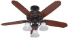
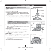
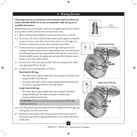
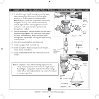
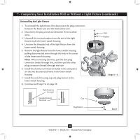
7 • Completing Your Installation With or Without a Multi Staked Light Fixture (Cont.) 7-6. To attach the lower switch housing, connect the upper plug connector from the motor to the lower plug connector in the lower switch housing assembly. Note: Both plug connectors are polarized and will only fit together one way. Make sure the connectors are properly aligned before connecting them. Incorrect connection could cause improper operation and damage to the product. 7-7. Place the lower switch housing assembly over the upper switch housing. Align the side screw holes in the upper and lower switch housings. Attach the lower switch housing to the upper switch housing with three housing assembly screws. 7-8. Remove the shade ring from each shade cup. 7-9. Install each glass shade in a shade cup. 7-10. Install and tighten the shade ring to secure the glass shade. Do not overtighten. 7-11. install candelabra bulbs (60 Watt Maximum) into the sockets. Plug Connector Detail Lower Switch Housing Shade Cup Steps 7-6 - 7-7 Shade Ring Housing Assembly Screw Note: In compliance with US federal energy regulations, this ceiling fan contains a device that restricts its light output. Exceeding the wattage limit marked on the MAX wattage sticker affixed to the light socket(s) may result in fire hazard or improper operation. Glass Shade Shade Ring Steps 7-9 - 7-10 13 42620-01 • 09/23/10 • Hunter Fan Company Shade Cup
-
 1
1 -
2
-
3
-
4
-
5
-
6
-
7
-
 8
8 -
 9
9 -
 10
10 -
 11
11 -
 12
12 -
 13
13 -
 14
14 -
 15
15 -
 16
16
 |
 |