Hunter 22563 Owner's Manual - Page 14
Uninstalling the Light Fixture
 |
View all Hunter 22563 manuals
Add to My Manuals
Save this manual to your list of manuals |
Page 14 highlights
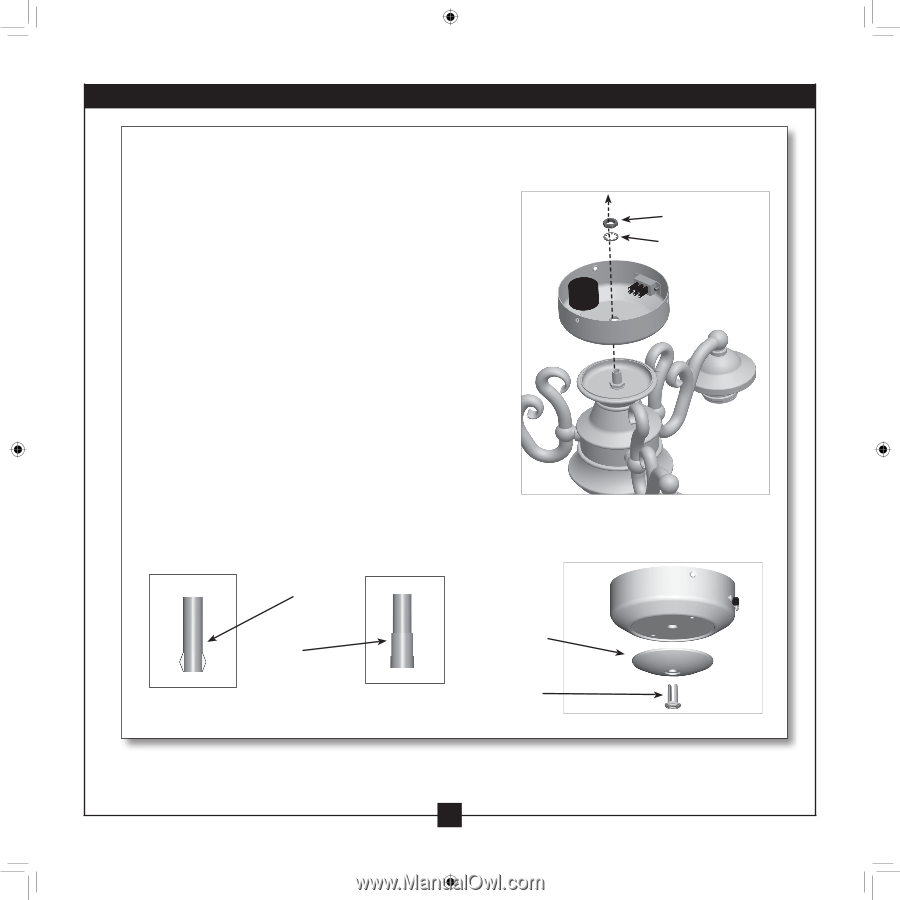
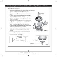
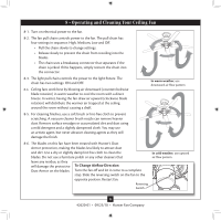
7 • Completing Your Installation With or Without a Light Fixture (continued) Uninstalling the Light Fixture 1. To uninstall the light fixture, first disconnect the plug connectors between the black wire and the black/white wire. 2. Disconnect the plug connectors between the two white wires. 3. Uninstall the nut and washer from the end of the light fixture inside the lower switch housing. 4. Unscrew the threaded rod of the light fixture from the lower switch housing. 5. Remove the light fixture from the lower switch housing pulling disconnected wires through the hole in the center of the lower switch housing. Note: When removing the wires, pull the thin plug connector (male) through first, and then pull the other plug connector (female) through the hole. 6. Install the dummy terminals (included in the sack parts) on the two disconnected wires in the lower switch housing. 7. Install the switch housing cap and plug button to the lower switch housing. 8. Continue with Step 7-6 on page 10. Male Dummy Terminal Female Dummy Cap Terminal Nut Washer Threaded Rod Steps 3 - 5 Plug Button Step 7 14 42620-01 • 09/23/10 • Hunter Fan Company
-
 1
1 -
2
-
3
-
4
-
5
-
6
-
7
-
8
-
 9
9 -
 10
10 -
 11
11 -
 12
12 -
 13
13 -
 14
14 -
 15
15 -
 16
16
 |
 |