Hunter 23856 User Guide - Page 2
Installation Instructions For, Hunter Original Ceiling Fans
 |
View all Hunter 23856 manuals
Add to My Manuals
Save this manual to your list of manuals |
Page 2 highlights
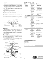
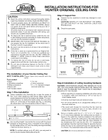
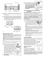
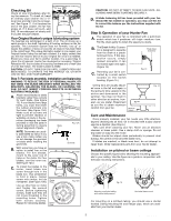
SINCE INSTALLATION INSTRUCTIONS FOR ® HUNTER ORIGINAL CEILING FANS 1 8 8 6 CAUTION: 1. Read this entire instruction manual thoroughly before beginning installation and SAVE THESE INSTRUCTIONS. 2. To avoid possible shock, BE CERTAIN ELECTRICITY IS SHUT OFF AT MAIN PANEL BEFORE WIRING. Always turn power off at main panel before servicing your fan or installing accessories. All wiring must be in accordance with national and local electrical codes. If you are unfamiliar with wiring, you should use a qualified electrician. 3. To reduce the risk of personal injury, install the fan only to the building structure according to these instructions, and use only the hardware supplied. 4. NEVER REST THE FAN ON THE SWITCH HOUSING. As you prepare the fan for installation, let the motor rest in the liner in which it was packed. 5. Be sure to put full contents of oil tube in fan according to instructions. 6. If this fan is used as a replacement for an Original Old- Tyme non-reversible fan, it must be installed per instructions included with this fan. DO NOT HANG ON SINGLE "J" HOOK. Failure to follow these instructions could result in fan falling. 7. To reduce the risk of noise do not use a solid-state speed control with this fan. Use Hunter controls only. 8. Do not use an abrasive cleaner on the fan. A mild detergent will clean and restore most units to their original beauty. Step 2: Inspect fan A. Unpack the fan carefully to avoid any damage to components. CAUTION: NEVER LIFT THE MOTOR BY THE WIRES. LET MOTOR REST IN THE CARTON LINER FOR PROTECTION. B. Check the sack parts. Bracket Pipe Nipple in Motor Carton Hanger Bracket Assembly Bracket Screws Blade Screws Blade Assembly Screws The installation of your Hunter Ceiling Fan NOTE TO INSTALLERS: Please leave this manual with the owner. Tools needed: • Pliers • 11/64" bit • Flat blade screwdriver • 3 wire connectors • Phillips screwdriver • 4" x 11/2" standard octagon • Electric drill electrical outlet box • 3/8" Socket wrench Step 1: Pre-installation A. Select installation site: Normally this is near the center of the room, often replacing a light fixture. Make certain that ample clearance is left for the rotating fan blades. For maximum efficiency, no obstruction (walls, posts, etc.) should be within 24" of the tips of the blades (see Fig. 1). Mounting site should also meet the precautions listed in Step 3. 12" minimum 24" clearance 84" min. to floor Fig. 1 B. Fan mounting height: Your Hunter fan comes with the proper hardware to hang the fan from a standard 8 foot ceiling so the fan blades will be 12" from the ceiling and approximately 7 feet from the floor (see Fig. 1). NOTE: On vaulted ceilings, up to 45° pitch, you may want to use the Hunter Vaulted Ceiling Mounting Kit. Canopy Screws Rubber Bushing with Pin Oil Fig. 2 Step 3: Installation of ceiling mounting hardware CAUTION: YOUR HUNTER CEILING FAN WEIGHS UP TO 50 LBS. THE FOLLOWING PRECAUTIONS MUST BE TAKEN FOR SAFETY AND TO ENSURE THAT YOUR FAN IS SECURELY MOUNTED TO THE CEILING. • When inspecting or preparing installation site where wiring is available, make sure electricity is "off" at fuse box or circuit breaker panel. • All wiring must meet local and national codes. • Do not mount directly to an unsupported ceiling or to an electrical outlet box. • The wood joist chosen for mounting the fan must be sound and of sufficient size. In no case, should it be smaller than standard 2" x 4" lumber. A. Secure a metallic outlet box 4" x 11/2" or 4" x 1/2" deep to 2 x 4 cross brace between two ceiling joists as shown in Figure 3. The outlet box must be recessed in the ceiling by 1/16" minimum. Secure the outlet box to the cross brace by drilling (2) pilot holes no larger than the minor diameter of the woodscrews (5/64") and use two #8 x 11/2" woodscrews and washers. Use the innermost holes for securing the box. Orient the box so the outermost holes are aligned with the 2 x 4 brace. The outermost holes will be used in Step 3B. CAUTION: Do not use a lubricant on screws. 41121-01 9/95 1 ©1993 HUNTER FAN CO.™
-
 1
1 -
 2
2 -
 3
3 -
 4
4
 |
 |
