Hunter 23856 User Guide - Page 3
Step 4: Hanging your fan, Step 5: Wiring instructions and canopy, installation, Canopy installation - ceiling fan
 |
View all Hunter 23856 manuals
Add to My Manuals
Save this manual to your list of manuals |
Page 3 highlights
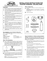
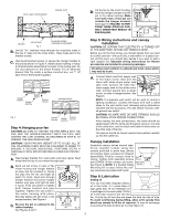
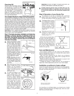
Set Screws 40mm x 80mm WOOD BRACE CEILING JOIST CEILING OUTLET BOX Fig. 3 M4 WOOD SCREW & WASHER (2) REQUIRED B. Drill (2) 11/64" diameter holes through the outermost holes in the box 2" deep into the cross brace. These holes are for the bracket screws. C. Use the (2) bracket screws to secure the hanger bracket to the joist as shown in Figure 4. Install rubber bushing in hanger bracket before assembling the parts to the ceiling joist. Do not use lubricant on the screw threads. For an alternate bracket that fits inside a surface-mounted box, cut 1" off each end of the bracket supplied. Hanger Bracket Rubber Bushing Bracket Screws Alternate Bracket Fig. 4 Hanger Bracket Bracket Rubber Screws Bushing Step 4: Hanging your fan CAUTION: BE SURE TO TIGHTEN THE PIPE NIPPLE INTO THE FAN, AND THE HANGER BRACKET ONTO THE PIPE, AND TIGHTEN THE 2 SET SCREWS, AS DESCRIBED IN STEP B, TO PREVENT THE FAN FROM FALLING. CAUTION: YOUR FAN MAY WEIGHT UP TO 50 LBS. ALL OF THE FOLLOWING STEPS MUST BE FOLLOWED IN ORDER TO ENSURE A SECURE MOUNTING. PERFORM STEPS A THROUGH D WITH MOTOR RESTING IN LINER FOR PROTECTION. A. Take hanger bracket from sack parts and pipe nipple. Feed wires from the top of your motor through pipe. B. Back out set screw in neck of fan Set motor housing and hanger bracket Screw Fig. 5 so pipe can be screwed in. Screw the pipe into the fan until tight (at least 41/2 turns). Feed wire through hanger bracket and screw hanger bracket onto pipe until tight (at least 3 turns). Then use pliers to tighten both hanger bracket and pipe together. Tighten the set screw in the motor housing with pliers. Securely tighten the set screw in the hanger bracket. See Figure 5. C. Be sure the pin rubber bushing. is centered in the See Figures 6 and 7. Bushing Pin Fig. 6 D. Lift the fan by the motor housing, hook the hanger bracket onto the pin in the rubber bushing. Make sure both ends of the pin are outside the hanger bracket. See Figure 9. FAILURE TO PERFORM THESE STEPS IN CORRECT ORDER MAY RESULT IN FAN FALLING. Bushing Pin Min. 84" to floor Fig. 7 Step 5: Wiring instructions and canopy installation CAUTION: BE CERTAIN THAT ELECTRICITY IS TURNED OFF AT THE MAIN PANEL BEFORE ANY WIRING IS DONE. Before you do the final wiring, you should decide how you want to control your fan-with pull cord, a wall switch or a speed control. At this point, you should also decide if you want to add a light adaptor kit. Separate wiring instructions for Hunter accessories are included in accessory packages. All wiring must conform to national and local codes which may vary by locale. A. Connect black electrical supply lead to the black motor lead and the black with white stripe motor lead (See note). Connect the white elec- trical supply lead to the white motor lead. Connect ground wire to green screw on side of hanger bracket. See Fig. 8 Figure 8. NOTE: If a separate wall switch will be used to control a lighting accessory, connect the black wire with a white stripe to the wall switch lead, following wiring instructions included with the accessory. The wall switch must be a listed general-use switch. CAUTION: NO BARE WIRE OR WIRE STRANDS SHOULD BE VISIBLE AFTER MAKING CONNECTIONS. After making the wire connections, the wires should be spread apart with the white and the green wires on one side of the outlet box, and the black and black & white wires on the other side of the box. The splices should be turned upward and pushed carefully up into the outlet box. Canopy installation Assemble canopy halves around pipe. Screw together loosely using two screws provided in parts bag. (Brass and antique brass canopies are shipped assembled.) Position canopy close to Set ceiling. Tighten both assembly screws Screw and SCREW IN the canopy set screw. Assembly See Figure 9. NOTE: If a Vaulted Ceiling Screw Mounting Kit is used, follow the can- Fig 9 opy instructions provided with the kit. Fig 10 Step 6: Lubrication Adding oil Your fan has been shipped without oil in the motor. A 1-ounce tube of high grade SAE 10 non-detergent oil is packaged in the sack parts. All the oil in the tube must be put into the fan. Cut the tip off the tube and place the tube into the oil hole. To avoid overflowing during filling, allow oil to gravity flow about one minute to fill the oil reservoir. (It may be necessary to puncture the tube to allow air in.) See Figure 10. 41121-01 9/95 2 ©1993 HUNTER FAN CO.™
-
 1
1 -
 2
2 -
 3
3 -
 4
4
 |
 |
