Hunter 82040 Owner's Manual - Page 8
bit
 |
View all Hunter 82040 manuals
Add to My Manuals
Save this manual to your list of manuals |
Page 8 highlights
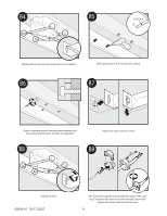
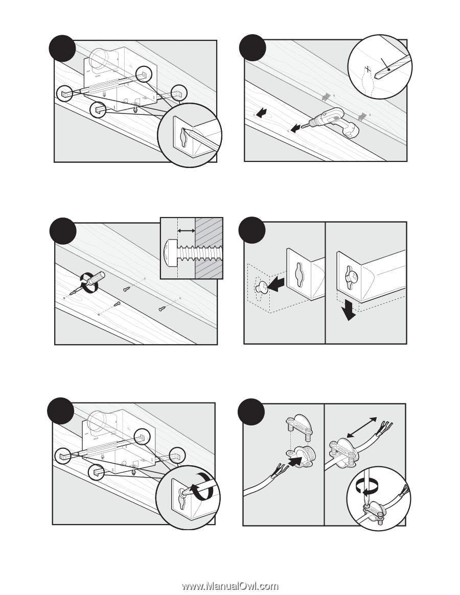
B4 B5 1/16" bit Mark position of screws by using holes as a template. Drill a pilot hole at the TOP of each outline. B6 B7 Insert mounting screws, leaving space between the screw head and the joist. (Screws are supplied.) Attach the rails onto the screws. B8 B9 3" Tighten screws. 42936-01 10/17/2007 Run the power supply wire through the strain relief, leaving 3" between the end of the wire and the strain relief. Tighten the strain relief around the wire. 8
-
 1
1 -
2
-
 3
3 -
 4
4 -
 5
5 -
 6
6 -
 7
7 -
 8
8 -
 9
9 -
 10
10 -
 11
11 -
 12
12 -
 13
13 -
14
-
15
-
16
-
17
-
18
-
19
-
20
-
21
-
22
-
23
-
24
-
25
-
26
-
27
-
28
-
29
-
30
-
31
-
32
-
33
-
34
-
35
-
36
 |
 |
42936-01
10/17/2007
8
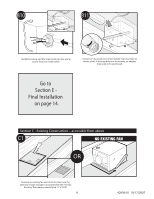
Mark position of screws by using holes as a template.
Drill a pilot hole at the TOP of each outline.
B4
1/16” bit
B5
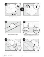
Insert mounting screws, leaving space between the
screw head and the joist. (Screws are supplied.)
Attach the rails onto the screws.
B6
B7
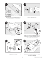
B8
Tighten screws.
Run the power supply wire through the strain relief, leav-
ing 3” between the end of the wire and the strain relief.
Tighten the strain relief around the wire.
3”
B9