Husqvarna 336FR Owners Manual - Page 14
Assembling the cutting, equipment, Fitting the guard extension, Fitting a blade guard, grass blade,
 |
View all Husqvarna 336FR manuals
Add to My Manuals
Save this manual to your list of manuals |
Page 14 highlights
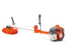
ASSEMBLY Push and hold the button (C). While securely holding the engine end, pull the attachment straight out of the coupling. Enter the guard extension guide in the slot of the combination guard. Then click the guard extension into position on the guard with the four quick-fasteners. C Assembling the cutting equipment WARNING! ! When fitting the cutting attachment it is extremely important that the raised section on the drive disc/support flange engages correctly in the centre hole of the cutting attachment. If the cutting attachment is fitted incorrectly it can result in serious and/or fatal personal injury. The guard extension is removed easily using the spark plug spanner, see illustration. Fitting a blade guard, grass blade and grass cutter G F E D ! WARNING! Never use a cutting attachment without an approved guard. See the chapter on Technical data. If an incorrect or faulty guard is fitted this can cause serious personal injury. IMPORTANT! If a saw blade or grass blade are to be used the machine must be equipped with the correct handlebar, blade guard and harness. Fitting the guard extension CAUTION! The guard extension shall always be fitted when using the trimmer head/plastic blades and combination guard. The guard extension shall always be removed when using the grass blade and combination guard. A B C A • Hook the blade guard/combination guard (A) onto the fitting on the shaft and secure with the bolt. CAUTION! Ensure that the guard extension is removed. Use the recommended blade guard. See the Technical data section. • Fit the drive disc (B) on the output shaft. • Turn the blade shaft until one of the holes in the drive disc aligns with the corresponding hole in the gear housing. • Insert the locking pin (C) in the hole to lock the shaft. • Place the blade (D), support cup (E) and support flange (F) on the output shaft. • Fit the nut (G). The nut must be tightened to a torque of 35-50 Nm (3.5-5 kpm). Use the socket spanner in 14 - English
-
 1
1 -
2
-
3
-
4
-
5
-
6
-
7
-
8
-
 9
9 -
 10
10 -
 11
11 -
 12
12 -
 13
13 -
 14
14 -
 15
15 -
 16
16 -
 17
17 -
 18
18 -
 19
19 -
20
-
21
-
22
-
23
-
24
-
25
-
26
-
27
-
28
-
29
-
30
-
31
-
32
-
33
-
34
-
35
-
36
-
37
-
38
-
39
-
40
-
41
-
42
-
43
-
44
 |
 |
