Husqvarna 535LST Owner Manual - Page 10
To assemble the loop handle, To assemble the cutting attachment guard and trimmer head,
 |
View all Husqvarna 535LST manuals
Add to My Manuals
Save this manual to your list of manuals |
Page 10 highlights
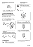
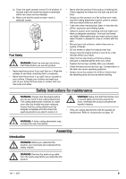
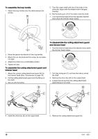
To assemble the loop handle 1. Attach the loop handle onto the shaft between the arrows. 5. Turn the output shaft until one of the holes in the drive disc aligns with the related hole in the gear housing. 6. Put the locking pin (C) in the hole to lock the shaft. 7. Turn the trimmer head (H) in the opposite direction from which the trimmer head rotates. H To disassemble the cutting attachment guard and trimmer head 1. Turn the trimmer head (H) in the direction from which the trimmer head rotates. 2. Move the spacer into the slot of the loop handle. 3. Attach the nut, the knob and the screw, do not make it to tight. 4. Adjust the product to a comfortable position. 5. Tighten the bolt. To assemble the cutting attachment guard and trimmer head 1. Attach the correct cutting attachment guard (A) for the trimmer head (See, Accessories on page 19). 2. Put the cutting attachment guard onto the fitting on the shaft. 3. Secure with the bolt(L). H 2. Pull the locking pin (C) out from the hole to unlock the shaft. 3. Remove the drive disc (B) on the output shaft. 4. Loosen the bolt (L) from the cutting attachment guard-fitting on the shaft. B B L C L C A 4. Install the drive disc (B) on the output shaft. A 5. Remove the cutting attachment guard (A). 10 1011 - 005 -
-
 1
1 -
2
-
3
-
4
-
 5
5 -
 6
6 -
 7
7 -
 8
8 -
 9
9 -
 10
10 -
 11
11 -
 12
12 -
 13
13 -
 14
14 -
 15
15 -
16
-
17
-
18
-
19
-
20
-
21
-
22
-
23
-
24
-
25
-
26
-
27
-
28
-
29
-
30
-
31
-
32
-
33
-
34
-
35
-
36
-
37
-
38
-
39
-
40
-
41
-
42
-
43
-
44
-
45
-
46
-
47
-
48
-
49
-
50
-
51
-
52
-
53
-
54
-
55
-
56
-
57
-
58
-
59
-
60
-
61
-
62
-
63
-
64
-
65
-
66
-
67
-
68
 |
 |
