Husqvarna YT48CS Operation Manual - Page 5
Assembly, Unassembled Parts
 |
View all Husqvarna YT48CS manuals
Add to My Manuals
Save this manual to your list of manuals |
Page 5 highlights
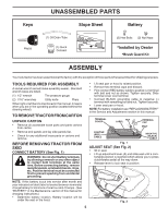
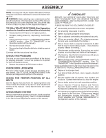
Keys UNASSEMBLED PARTS Slope Sheet Battery Key(s) (1) Oil Drain Tube (1) Quick Connect (2) Hex Bolts (2) Nut Keps *Installed by Dealer *Brush Guard Kit ASSEMBLY Your new tractor has been assembled at the factory with the exception of those parts left unassembled for shipping purposes. TOOLS REQUIRED FOR ASSEMBLY A socket wrench set will make assembly easier. Standard wrench sizes are listed. (1) 1/2" wrench Tire pressure gauge (2) 7/16" wrenches Utility knife Pliers When right or left hand is mentioned in this manual, it means when you are in the operating position (seated behind the steering wheel). TO REMOVE TRACTOR FROM CARTON UNPACK CARTON • Remove all accessible loose parts and parts cartons from carton. • Remove end panels and lay side panels flat. • Check for any additional loose parts or cartons and remove. BEFORE REMOVING TRACTOR FROM SKID CONNECT BATTERY (See Fig. 1) WARNING: Do not short battery terminals by allowing a wrench or any other object to contact both terminals at the same time. Before connecting battery, remove metal bracelets, wristwatch bands, rings, etc. Positive terminal must be connected first to prevent sparking from accidental grounding. NOTE: If this battery is put into service after month and year indicated on label (label is located between terminals) charge battery for minimum of one hour at 6-10 amps. (See "BATTERY" in the Maintenance section of this manual for charging instructions.) • Determine battery location. Battery location will be under the seat or the hood. • Lift seat pan or hood to raised position. • Remove two terminal caps and discard. • First connect RED battery cable to positive (+) terminal with bolt and nut as shown. Tighten securely. Slide terminal cover over terminal. • Connect BLACK grounding cable to negative (-) terminal with remaining bolt and nut. Tighten securely. • Lower seat pan or hood. NOTE: For battery installation see "REPLACING BATTERY" in the Service and Adjustments section in this manual. TERMINAL COVER NUT LABEL TERMINAL CAP BOLT POSITIVE (RED) CABLE 02605 NEGATIVE (BLACK) CABLE Fig. 1 ADJUST SEAT (See Fig. 2) • Sit in seat. • Lift up adjustment lever (A) and slide seat until a comfortable position is reached which allows you to press clutch/brake pedal all the way down. • Release lever to lock seat in position. A Fig. 2 5
-
 1
1 -
 2
2 -
 3
3 -
 4
4 -
 5
5 -
 6
6 -
 7
7 -
 8
8 -
 9
9 -
 10
10 -
 11
11 -
12
-
13
-
14
-
15
-
16
-
17
-
18
-
19
-
20
-
21
-
22
-
23
-
24
-
25
-
26
-
27
-
28
-
29
-
30
-
31
-
32
-
33
-
34
-
35
-
36
-
37
-
38
-
39
-
40
-
41
-
42
-
43
-
44
-
45
-
46
-
47
-
48
-
49
-
50
-
51
-
52
-
53
-
54
-
55
-
56
-
57
-
58
-
59
-
60
 |
 |
