Icom IC-R9500 Service Manual - Page 11
FREQUENCY SYNTHESIZR, VIDEO AM-DEMODULATION- except for USA version
 |
View all Icom IC-R9500 manuals
Add to My Manuals
Save this manual to your list of manuals |
Page 11 highlights
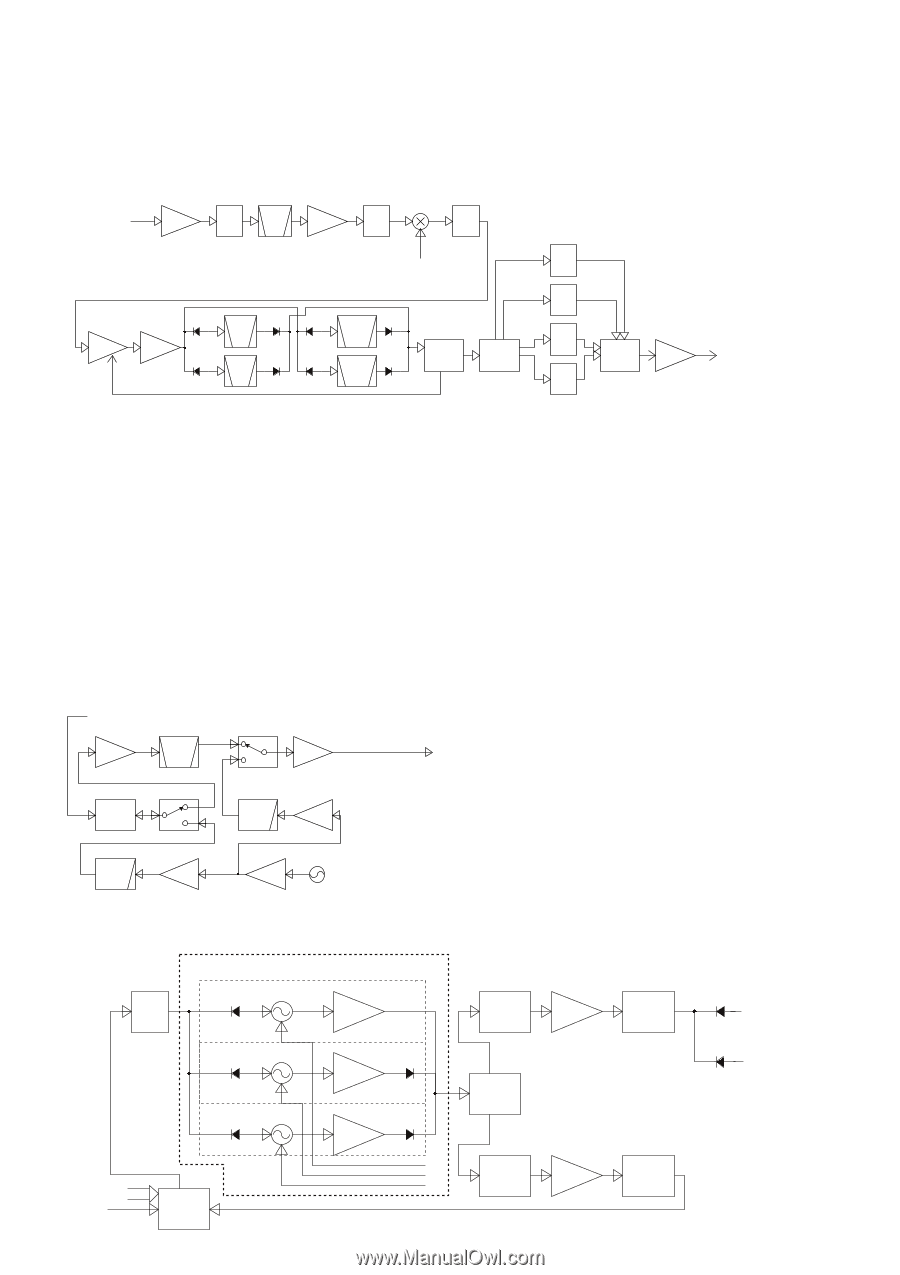
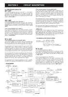
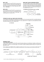
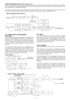
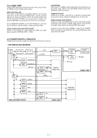
-VIDEO AM-DEMODULATION- (except for USA version) The 2nd IF signal divide at the splitter is amplified and filtered, then converted into the 3rd IF (video IF) signal at 3rd mixer (IC2201). The converted video IF signal is amplified, then passed through the video IF filters. The filtered video IF signal is applied to the video demodulation IC and AM-demodulated. The demodulated video signals are passed through Band Eliminate Filter (BEF; as the trap) to remove unwanted beat components. The filtered signal is buffer-amplified and output from the video jack on the CONNECT-B UNIT. • VIDEO AM-DEMODULATION CIRCUIT -10dBm Q2101 2nd IF signal IF AMP ATT from the RF-A UNIT Q2181 BPF IF AMP SPM5001 IC2201 ATT ATT 48MHz 2nd LO signal from the PLL UNIT TR4_5M TRAP TPSCC4.5MB TR5_5M TRAP TPSCC5.5MB Q1 IF AMP Q2 BUFF TR4_5M BPF BPF TR5_5M AGC TR6_0M BPF BPF TR6_5M IC101 VIDEO DETECT TPSCC6.0MB TR6_0M TRAP FILTER SW FILTER SW IC201/IC203 TRAP IC202/IC204 Q301 BUFF Composit video signal to the J601 (CONNECT-B UNIT) TR6_5M TPSCC6.5MB 3-2 FREQUENCY SYNTHESIZER OSC UNIT The OSC UNIT supplies very high stability 10.000000 MHz standard frequency signal generated by the OCXO (Oven Controlled X'tal Oscillator). The oscillated reference frequency signal is buffer-amplified and amplified and filtered to remove harmonic components at the LPF. The filtered reference frequency signal is applied to the PLL UNIT via the buffer. The reference frequency signal is also available from the external reference frequency source (10.000000 MHz) via [REF I/O] (CONNECT-B UNIT; J201). The reference frequency signal from the CONNECT-B UNIT is passed through the attenuators, BPF and switches, then bufferamplified before being applied to the PLL UNIT. • OSC CIRCUITS From [REF I/O] (CONNECT-B; J201) Q61/Q62 10MHz AMP BPF EXT-REF IN 10.000.000 MHz BUFF Standard signal Q70 ATT EXT-REF OUT LPF 10MHz AMP Q42 LPF 10MHz AMP Q22 2SC4081 Q21 BUFF X1 (10.000000MHz OCXO) PLL UNIT PLL UNIT supplies the LO (Local Oscillator) signals (1st, 2nd, 3rd and 4th), still more the clock signals for DSP circuits. To obtain physical strength for the VCO1, VCO2, DOUBLER, FIL1 and FIL2 BOARDs, these circuits are shielded and isolated perfectly, by being patterned separately on different P.C. boards. VCO1 BOARD VCO1 BOARD has tree VCOs ;VCO-A, VCO-B and VCO-C. VCO-A (Q1301), as an example, is a colpitts-typed oscillator circuit, and its output signal is buffered by Q1302 and output via diode switch. Q1303 controls the power supply for the VCO, and the voltage of LH3V line adjusts the oscillation level for suitable LO signal level. The buffer-amplified VCO output signals are divided by the divider, and applied to the LO amplifier via attenuator (as a pad). The amplified LO signals are applied to the RF-A UNIT or FIL1 BOARD as the 1st LO signals, via filters and amplifiers. The VCO-A is mounted on the nearest to VCO1 board to reduce the signal loss. The resonators are employed strip lines which had been used with SMD electric parts. The oscillating frequency ranges are divide into three for wide oscillation frequency coverage. • VCO-A, VCO-B, VCO-C LOOP VCO1 BOARD IC1001 LOOP FIL 317.8~391.3MHz VCO-C Q1101 Q1102 BUFF 317.8~639.35MHz IC1300 ATT AMP ATT 389.35~521.3MHz VCO-B Q1201 Q1202 BUFF 6dB HYB 514.35~639.35MHz VCO-A Q1301 Q1302 BUFF Ref 500kHz DATA CK PST1P 10.5MHz IC1000 PLL IC LH1V LH2V LH3V IC1351 ATT AMP ATT 317.8~639.35MHz 3 - 3 1st LO signals to RF-A UNIT To FIL1 BOARD
-
 1
1 -
2
-
3
-
4
-
5
-
 6
6 -
 7
7 -
 8
8 -
 9
9 -
 10
10 -
 11
11 -
 12
12 -
 13
13 -
 14
14 -
 15
15 -
 16
16 -
17
-
18
-
19
-
20
-
21
-
22
-
23
-
24
-
25
-
26
-
27
-
28
-
29
-
30
-
31
-
32
-
33
-
34
-
35
-
36
-
37
-
38
-
39
-
40
-
41
-
42
-
43
-
44
-
45
-
46
-
47
-
48
-
49
-
50
-
51
-
52
-
53
-
54
-
55
-
56
-
57
-
58
-
59
-
60
-
61
-
62
-
63
-
64
-
65
-
66
-
67
-
68
-
69
-
70
-
71
-
72
-
73
-
74
-
75
-
76
-
77
-
78
-
79
-
80
-
81
-
82
-
83
-
84
-
85
-
86
-
87
-
88
-
89
-
90
-
91
-
92
-
93
-
94
-
95
-
96
-
97
-
98
-
99
-
100
-
101
-
102
-
103
-
104
-
105
-
106
-
107
-
108
-
109
-
110
-
111
-
112
-
113
-
114
-
115
-
116
-
117
-
118
-
119
-
120
-
121
-
122
-
123
-
124
-
125
-
126
-
127
-
128
-
129
-
130
-
131
-
132
-
133
-
134
-
135
-
136
-
137
-
138
 |
 |