Icom IC-V8000 Instruction Manual
Icom IC-V8000 Manual
 |
View all Icom IC-V8000 manuals
Add to My Manuals
Save this manual to your list of manuals |
Icom IC-V8000 manual content summary:
- Icom IC-V8000 | Instruction Manual - Page 1
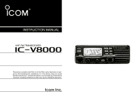
INSTRUCTION MANUAL VHF FM TRANSCEIVER iV8000 This device complies with Part 15 of the FCC rules. Operation is subject to the following two conditions: (1) This device may not cause harmful interference, and (2) this device must accept any interference received, including interference that - Icom IC-V8000 | Instruction Manual - Page 2
. The IC-V8000 VHF FM TRANSCEIVER is designed and built with Icom's superior technology and craftsmanship. With proper care, this product should provide you with years of trouble-free operation. We want to take a couple of moments of your time to thank you for making your IC-V8000 your radio of - Icom IC-V8000 | Instruction Manual - Page 3
radio equipment con- taining a transmitter. During mobile operation, DO NOT operate the transceiver without running the vehicle's engine. When the transceiver's power damage the transceiver's surfaces. USE Icom microphones only (supplied or optional). Other man- ufacturer's microphones have different - Icom IC-V8000 | Instruction Manual - Page 4
CAUTIONS ii SUPPLIED ACCESSORIES iii TABLE OF CONTENTS iii QUICK REFERENCE GUIDE I-VI Installation I Your first contact IV Repeater operation V Programming memory VI 1 PANEL DESCRIPTION 1-8 Front panel 1 Function display 3 Rear panel 5 Microphone (HM-133V 6 Microphone keypad 7 2 SETTING - Icom IC-V8000 | Instruction Manual - Page 5
52 Code programming 52 7 Pager operation 55 Code squelch 57 8 12 OTHER FUNCTIONS 58-70 Set mode 58 9 Initial set mode 62 Weather channel operation 65 10 Microphone keys 67 11 Partial reset 68 All reset 68 12 Data cloning 69 13 MAINTENANCE 71-73 13 Troubleshooting 71 - Icom IC-V8000 | Instruction Manual - Page 6
GUIDE Installation D Location Select a location which can support the weight of the transceiver and does not interfere with driving in any way. We recommend the locations shown in the diagram below. NEVER place the transceiver where normal operation the function display. Nut Spring washer Flat washer - Icom IC-V8000 | Instruction Manual - Page 7
for the cable connections. Supplied DC power cable Solder D DC power supply connection Use a 13.8 V DC power supply with at least 15 A capacity. Make sure the ground terminal of the DC power supply is grounded. • CONNECTING TO A DC POWER SUPPLY • See p. 72 for fuse replacement. IC-V8000 to an - Icom IC-V8000 | Instruction Manual - Page 8
their installation. Check with your local dealer for more information and recommendations. D Connecting a microphone Connect a microphone to the eight-pin modular socket on the front panel of the transceiver. *HM-133V; A different microphone may be supplied with some versions of the IC-V8000. III - Icom IC-V8000 | Instruction Manual - Page 9
the air. We would like to take you through a few basic operation steps to make your first "On The Air" an enjoyable experience. 1. Turning ON the transceiver Before powering up your IC-V8000, you may want to make sure the audio volume and squelch level controls are set in 9-10 o'clock positions. Set - Icom IC-V8000 | Instruction Manual - Page 10
QUICK REFERENCE GUIDE Repeater operation 1. Setting duplex Push [LOW(DUP)] for 1 sec. once or twice to select minus duplex or plus duplex. • The USA and CSA versions have an auto - Icom IC-V8000 | Instruction Manual - Page 11
QUICK REFERENCE GUIDE Programming memory channels The IC-V8000 has a total of 200 memory channels (including 6 scan edges and 1 call channel) for storing often used operating frequency, repeater settings, etc. 1. Setting a frequency In VFO mode, set the desired operating frequency with repeater, - Icom IC-V8000 | Instruction Manual - Page 12
Turns power ON and OFF when pushed for 1 sec. w MEMORY/CALL•PRIORITY SWITCH [M/CALL(PRIO)] ➥ Push to select and toggle memory, call and weather channel* modes. (pgs. 24, 35, 65) *Weather channels available for USA versions only. ➥ Starts priority watch when pushed for 1 sec. (p. 44) 1 e MICROPHONE - Icom IC-V8000 | Instruction Manual - Page 13
12) i TUNING DIAL [DIAL] Selects the operating frequency (p. 9), memory channel (p. 24), the setting of the set mode item and the scanning direction (p. 38). o MEMORY WRITE SWITCH [MW(S.MW)] (p. 25) ➥ Selects a memory channel for programming. ➥ Programs the selected memory channel when pushed for - Icom IC-V8000 | Instruction Manual - Page 14
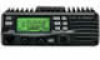
PTT function. (p. 16) e OUTPUT POWER INDICATORS "LOW" appears when low output power; "LOW" and "MID" appear when low mid output power; "MID" appears when middle output power is selected w FREQUENCY READOUT Shows the operating frequency, channel names, set mode contents, etc. • Frequency decimal - Icom IC-V8000 | Instruction Manual - Page 15
when plus duplex, "-" appears when minus duplex operation is selected. !4 AUTO POWER-OFF INDICATOR (p. 64) Appears while the auto power-off function is in use. !5 NARROW MODE INDICATOR (p. 61) Appears when the narrow mode is selected. Narrow mode is available with some USA versions only. 4 - Icom IC-V8000 | Instruction Manual - Page 16
when operating in a vehicle. The plug may cause voltage drops and ignition noise may be superimposed onto transmit or receive audio. e COOLING FAN Rotates while transmitting. Also rotates while receiving depending on the setting in set mode and transceiver's temperature. (p. 61) r ANTENNA CONNECTOR - Icom IC-V8000 | Instruction Manual - Page 17
DTMF MEMORY SELECT SWITCH [DTMF-S] (p. 46) o FUNCTION SWITCHES [F-1]/[F-2] (p. 67) Program and re-call your desired transceiver conditions. !0 BANK/OPTION SWITCH [BANK/OPTION] ➥ Push to selects memory bank condition during memory mode. (p. 32) ➥ Push for 1 sec. to select and toggle pager and code - Icom IC-V8000 | Instruction Manual - Page 18
PANEL DESCRIPTION Microphone keypad KEY FUNCTION SECONDARY FUNCTION ( +key) Switches between opening and closing the In memory mode switches the power. Selects mid. output power. Selects low output power Selects minus duplex operation. Selects plus duplex operation. Selects simplex operation - Icom IC-V8000 | Instruction Manual - Page 19
for program- ➥ Cancels the scan or priority watch. ming. (p. 26) (pgs. 38, 44) ➥ Advances the memory channel number ➥ Exit set mode. after entering set mode. (p. 58) Adjusts the squelch level increments. Mutes the audio. (p. 14) (p. 13) • Mute function is released when any oper- ation is - Icom IC-V8000 | Instruction Manual - Page 20
scan function. If scan starts, push [V/MHz(SCAN)] again to can- cel it. The display shows that the 1 MHz tuning step is selected. ➥ Push [VFO/LOCK] to select VFO mode. VFO/LOCK 9 Note that in this manual, sections beginning with a microphone icon (as above), designate operation via the HM133V - Icom IC-V8000 | Instruction Manual - Page 21
Using the keypad The frequency can be directly set via numeral keys on the mi- crophone. z Push [VFO/LOCK] to VFO mode, if necessary. ENT x Push [ENT C(T-OFF)] to activate the keypad for C digit input. c Push 6 keys to input a frequency. • When a digit is mistakenly input, push [ENT C(T- - Icom IC-V8000 | Instruction Manual - Page 22
2 SETTING A FREQUENCY Tuning step selection USING SET MODE Tuning steps are the minimum frequency change increments when you rotate the tuning dial or push [Y]/[Z] on the microphone. The following tuning steps are available. • 5 kHz • 20 kHz • 10 kHz • 25 kHz • 12.5 kHz • 15 kHz • 30 kHz • 50 - Icom IC-V8000 | Instruction Manual - Page 23
16KEY-L switch the microphone keypad lock function ON and OFF. • [PTT], [VFO/LOCK], [MR/CALL], [BANK/OPTION], [Y], [Z], [F-1], [F-2], [DTMF-S] and [FUNC] on the microphone can be used. • All switches on the transceiver can be used. • The keypad lock function is released when the power is turned OFF - Icom IC-V8000 | Instruction Manual - Page 24
operation. r Set the operating frequency. (pgs. 9, 10) t When receiving a signal on the set frequency, squelch opens and the transceiver emits audio to weak signals without disturbing the squelch setting or to open the squelch manually even when mute functions such as the tone squelch are in use. - Icom IC-V8000 | Instruction Manual - Page 25
to mute audio signals. • "MUTE" appears. • Push [CLR A(MW)] (or any other key) to cancel the function. Appears Squelch attenuator The transceiver has an and fully clockwise position. • When setting the squelch from the microphone, a level greater than '19' activates the squelch attenuator. - Icom IC-V8000 | Instruction Manual - Page 26
. IMPORTANT! (for 75 W transmission): The IC-V8000 is equipped with protection circuit to protect the power amplifier circuit from high SWR (Standing Wave Ratio) and temperature. When a high SWR antenna or no antenna is connected, or when the transceiver temperature becomes extremely high, the - Icom IC-V8000 | Instruction Manual - Page 27
The PTT switch can be operated as a one-touch PTT switch (each push switches between transmit/receive). Using this function you can transmit without pushing and holding the PTT switch. To prevent accidental, continuous transmissions with this function, the transceiver has a time-out timer. See - Icom IC-V8000 | Instruction Manual - Page 28
see p. 20. r Push and hold [PTT] to transmit. • The displayed frequency automatically changes to the transmit frequency (repeater input frequency). • If the other station's transmit signal can be received directly. uTo return to simplex operation, push [LOW(DUP)] for 1 sec., once or twice, to clear - Icom IC-V8000 | Instruction Manual - Page 29
. b Release [PTT] to receive. n Push [MONI 1(ANM)] to check whether the other station's transmit signal can be received directly. REPEATER OPERATION 4 m Push [SIMP 9(TSQL)] to return to simplex opera- SIMP tion. 9 • "+" or "-" indicator disappears. , To turn OFF the subaudible tone encoder - Icom IC-V8000 | Instruction Manual - Page 30
times until " " and "rt" appears; or until " " and "Ct" appears for tone squelch or pocket beep use. • When "d" is displayed in place of the 100 MHz digit, cancel the DTMF memory encoder in advance. (p. 46) z Set the mode/channel you wish to set the sub- SET audible tones to, such as VFO - Icom IC-V8000 | Instruction Manual - Page 31
46) • Push [DTMF-S] again to return the keypad to normal function control. • The transceiver has 10 DTMF memory channels for autopatch operation. See p. 45 for details. Push , then push desired keys. D 1750 Hz tone The microphone has 1750 Hz tone capability, used for ring tone when calling, etc - Icom IC-V8000 | Instruction Manual - Page 32
other stations by inhibiting your transmission when a signal is received. The transceiver has two inhibiting conditions, repeater and busy. q Push [PWR] to turn power OFF. w While pushing [SET(LOCK)], turn power ON to enter initial set mode. [SET(LOCK)] e Rotate the tuning dial to set the desired - Icom IC-V8000 | Instruction Manual - Page 33
[SET(LOCK)] or [MW(S.MW)] several times until the "REV" display appears as shown below. e Rotate the tuning dial to turn the repeater lockout function to ON or OFF. REPEATER OPERATION 4 z Push [SET B(D-OFF)] to enter set mode. SET x Push [SET B(D-OFF)] or [ENT C(T-OFF)] until B "REV" appears - Icom IC-V8000 | Instruction Manual - Page 34
the auto repeater function ON/OFF q Push [PWR] to turn power OFF. w While pushing [SET(LOCK)], turn power ON to enter initial set mode. While pushing [SET(LOCK)], turn power ON. e Push [SET(LOCK)] several times until the "RPT" display appears as shown above right. r Rotate the tuning dial to turn - Icom IC-V8000 | Instruction Manual - Page 35
General description The transceiver has 207 memory channels including 6 scan edge memory channels (3 pairs), and 1 call channel. Each of these channels can be individually programmed with operating frequency (pgs. 9, 10), duplex direction (p. 19) and offset (p. 21), subaudible tone encoder - Icom IC-V8000 | Instruction Manual - Page 36
5 MEMORY OPERATION Programming a memory channel VFO settings, including the set mode contents such as subaudible tone frequency, etc., can be programmed into a memory channel. q Set the desired frequency in VFO mode. ➥ Push [V/MHz(SCAN)] to select VFO mode. ➥ Set the frequency using the tuning - Icom IC-V8000 | Instruction Manual - Page 37
MEMORY OPERATION 5 D Programming a memory channel via the microphone The microphone can also be used to program memMW ory channels. z Set the desired frequency in VFO mode. ➥ Push [VFO/LOCK] to select VFO mode. ➥ Set the frequency using the keypad. ➥ Set other data (e.g. offset frequency, duplex - Icom IC-V8000 | Instruction Manual - Page 38
[EXAMPLE]: Transferring memory channel 30 contents to VFO. Front panel operation: Push M/CALL PRIO to select memory mode. Rotate for selecting memory channel. Push MW S.MW for 1 sec. HM-133V operation: Push to select memory mode. Select memory channel. 27 Push then push for 1 sec. - Icom IC-V8000 | Instruction Manual - Page 39
MEMORY OPERATION 5 D Memory/call➪call/memory q Select the memory/call channel to be transferred. ➥ Push [M/CALL(PRIO)] to select memory mode, then rotate the tuning dial to select the desired memory channel. ➥ Push [M/CALL(PRIO)] for 1 sec. to select the call channel. w Push [MW(S.MW)] momentarily. - Icom IC-V8000 | Instruction Manual - Page 40
select the memory channel to be cleared. • Memory channels not yet programmed are blank. r Push [MW(S.MW)] momentarily, then push [MW(S.MW)] again for 1 sec. This operation must be performed within 1.5 sec. • 3 beeps sound, then the frequency is cleared. • "M" indicator blinks continuously. • When - Icom IC-V8000 | Instruction Manual - Page 41
OPERATION 5 Programming channel names Each memory channel and the call channel can be programmed mode. • 1 short and 1 long beep sound. r Push [SET(LOCK)] to select the channel name programming are displayed. i Push [V/MHz(SCAN)] to program the name and exit the channel name programming condition. - Icom IC-V8000 | Instruction Manual - Page 42
OPERATION Channel names can also be programmed via the microphone. z Select the memory/call channel to be assigned memory names. ➥ Push [MR/CALL] to select memory mode desired channel names are displayed. m Push [CLR A(MW)] to program the name and exit the channel name programming condition. , Push - Icom IC-V8000 | Instruction Manual - Page 43
Rotate the tuning dial to select the contents in the bank. • No channel numbers are displayed for memory bank operation. y To return to regular memory condition, push [BANK(OPT)] twice. z Push [MR/CALL] to select memory mode, BANK/OPTION if desired. ➥ Push [MR/CALL] for 1 sec. to select the call - Icom IC-V8000 | Instruction Manual - Page 44
5 MEMORY OPERATION Memory bank setting q Push [M/CALL(PRIO)] to select memory mode, then select the desired memory channel via the tuning dial. w Push [BANK(OPT indication blinks as follows. e Push [BANK(OPT)] again to set the channel - Icom IC-V8000 | Instruction Manual - Page 45
: Even if the memory bank contents are cleared, the memory channel contents still remain programmed. q Select the desired bank contents to be transferred or erased. ➥ Push [M/CALL(PRIO)] to select memory mode. ➥ Push [BANK(OPT)] then rotate the tuning dial to select the desired memory bank - Icom IC-V8000 | Instruction Manual - Page 46
OPERATION Call channel selection Push [M/CALL(PRIO)] several times to select the call channel. ➥ Push [M/CALL(PRIO)] several times to select the call channel. • "C" appears instead of memory channel number indication. • Push [M/CALL(PRIO)] once or twice to select memory mode been programmed into - Icom IC-V8000 | Instruction Manual - Page 47
[Y]/[Z] v Push [FUNC] then [CLR A(MW)] for 1 sec. to program. • 3 beeps sound and the unit returns to VFO mode automatically. [EXAMPLE]: Programming 145.120 MHz into the call channel via the microphone. Push to select VFO mode. Set the frequency. Push , then . Push until large "C" appears - Icom IC-V8000 | Instruction Manual - Page 48
purposes. There are 3 scan types and 4 resume conditions to suit your operating needs. FULL SCAN (p. 38) Band edge Scan Repeatedly scans all frequencies . Jump PROGRAMMED SCAN (p. 38) Band edge Scan edges Scan Jump Band edge Repeatedly scans between two user-programmed frequencies. Used - Icom IC-V8000 | Instruction Manual - Page 49
2 or more memory channels (pgs. 25, 26); set skip settings, if desired (p. 41). D Operation q Select VFO mode for full/programmed scan with [V/MHz(SCAN)]; or memory mode for memory scan with [M/CALL(PRIO)]. • Select the desired bank with [BANK(OPT)] for bank scan. w Set the squelch to the point - Icom IC-V8000 | Instruction Manual - Page 50
OPERATION Scan edges programming Scan edges can be programmed in the same manner as memory channels. Scan edges are programmed into scan edges, 1A/1b to 3A/3b, in memory channels. q Set the edge frequency of the desired frequency range in VFO mode sec. to program. • 3 beeps sound and VFO is automatically - Icom IC-V8000 | Instruction Manual - Page 51
SCAN OPERATION 7 D Programming scan edges via microphone z Set the desired frequency in VFO mode. MW ➥ Push [VFO/LOCK] to select VFO mode. ➥ Set the frequency via the keypad or [Y]/[Z]. x Push [FUNC] then [CLR A(MW)] momentarily. c Push [Y] or [Z] to select scan edge channels, 1A, 2A or 3A. v Push - Icom IC-V8000 | Instruction Manual - Page 52
7 SCAN OPERATION Skip channel setting USING SET MODE The memory skip function speeds up scanning by checking only those memory channels not set as skip channels. Set skip channels as follows. The display shows that memory channel 1 is set as a skip channel. q Select a memory channel: ➥ Push [M/CALL( - Icom IC-V8000 | Instruction Manual - Page 53
sec. later. r Push [TONE(T-SCAN)] to exit set mode. SCAN OPERATION 7 z Push [SET B(D-OFF)] to enter set mode. SET x Push [SET B(D-OFF)] or [ENT C(T-OFF v Push [CLR A(MW)] to exit set mode. NOTE: Set mode cannot be accessed when memory names are displayed. To set the scan resume condition, return - Icom IC-V8000 | Instruction Manual - Page 54
See previous page for details. NOTES: ➧ If the pocket beep function is activated, the transceiver automatically selects the tone squelch function when priority watch starts. MEMORY CHANNEL WATCH While operating on a VFO fre- 5 sec. quency, priority watch checks for a signal on the selected memory - Icom IC-V8000 | Instruction Manual - Page 55
manually. r Push [M/CALL(PRIO)] while the display shows the mem- ory channel to stop the watch. While pausing or receiving a signal on the memory or call channel, "PRIO" and decimal point blink. PRIORITY WATCH 8 z Select VFO mode; then, set an operating watch. • The transceiver checks the memory - Icom IC-V8000 | Instruction Manual - Page 56
9 DTMF MEMORY ENCODER Programming a DTMF code DTMF codes are used for autopatching, controlling other equipment, etc. The transceiver has 10 DTMF memory channels (d0-d9) for storage of often-used DTMF codes of up to 24 digits. z Push [FUNC] then [LOW 6(DTMF)] to - Icom IC-V8000 | Instruction Manual - Page 57
di- rect selection ON. • The function indicator (microphone) lights green. c Push the desired DTMF channel NOTE: When no DTMF code programmed DTMF-S channel number is pushed, B(D-OFF)] to cancel the DTMF memory encoder. D Manual transmission z Deactivate the DTMF memory encoder by 9 DTMF - Icom IC-V8000 | Instruction Manual - Page 58
DTMF characters can be set to accommodate operating needs. The display shows the fastest DTMF speed is selected. q Push [PWR] for 1 sec. to turn power OFF. w While pushing [SET(LOCK)], push [PWR] for 1 sec. to turn power ON and enter initial set mode. e Push [SET(LOCK)] or [MW(S.MW)] several - Icom IC-V8000 | Instruction Manual - Page 59
you that someone has called while you were away from the transceiver. D Waiting for a call from a specific station q Set the operating frequency. w Push [SET(LOCK)] to enter set mode. y Push [TONE(T-SCAN)] several times until " " or " " are displayed to turn ON the pocket beep with tone squelch or - Icom IC-V8000 | Instruction Manual - Page 60
z Set the operating frequency. TSQLS x Program the CTCSS tone frequency or DTCS code in set mode. ➥ Push [SET B(D-OFF)] to enter set mode. DTCSS ➥ squelch, respectively. v When a signal with the matched tone is received, the transceiver emits beep tones for 30 sec. and blinks " ". b Push [PTT] to - Icom IC-V8000 | Instruction Manual - Page 61
mode. • See p. 48 for programming details. e Push [TONE(T-SCAN)] several times until " " or " " appears in the function display. • " " for tone squelch; " " for DTCS squelch operation strength. • To open the squelch manually, push [MONI(ANM)]. t Operate the transceiver in the normal way (push [PTT - Icom IC-V8000 | Instruction Manual - Page 62
the squelch opens and the tone frequency is temporarily programmed into the selected condition such as memory or call in step w. - No indication : Cannot be used for operation. -" " : CTCSS tone encoder -" " : CTCSS tone mode such as memory or call channel. b Push [CLR A(MW)] to stop the scan. - Icom IC-V8000 | Instruction Manual - Page 63
. Pager selective code (push [PTT]) Beep Beep Beep Answer back (manual) Beep Beep Beep Set both transceivers to either code squelch or non-coded operation Communication Code programming Optional UT-108 required D Before programming The pager and code squelch functions require ID codes and - Icom IC-V8000 | Instruction Manual - Page 64
OPT)] for 1 sec. Pager mode indication w Push [SET(LOCK)]. • One of either "CP" or "C0" to "C6" flashes. • "C0" is the ID code and "C1" to "C6" are transmit codes. e Rotate the tuning dial to select code channel C0. • A different ID code must be programmed into each transceiver. y Push [MW(S.MW)] to - Icom IC-V8000 | Instruction Manual - Page 65
[BANK/OPTION] for 1 sec. to select BANK/OPTION pager mode. • 100 MHz digit shows "P." x Push [SET B(D-OFF)] to enter to the code set mode. • One of either "CP" or "C0" to "C6 programmed for "receive inhibit," otherwise the transceiver will not reject unnecessary calls. • Pager/code squelch operation - Icom IC-V8000 | Instruction Manual - Page 66
z Program the desired code channel in adBANK/OPTION vance (p. 54). x Set the operating frequency. c Push [BANK/OPTION] for 1 sec. to select pager mode. . n Wait for an answer back. • When the transceiver receives an answer back code, the function display shows the other member's ID or group code. m - Icom IC-V8000 | Instruction Manual - Page 67
code squelch operation, or repeat the previous key operation again to select non-selective calling system. z Set the operating frequency. BANK display appears when you are called with the group code, 888, and 888 has been programmed into code channel C6. 11 • ERROR INFORMATION When the transceiver - Icom IC-V8000 | Instruction Manual - Page 68
transmit code channel: ➥ Push [SET(LOCK)]. ➥ Rotate the tuning dial to select the code channel. ➥ Push [TONE(T-SCAN)] to exit code set mode. r Operate the transceiver in the normal way (push [PTT] to transmit; release [PTT] to receive). t To cancel the code squelch, push [BANK(OPT)] for 1 sec - Icom IC-V8000 | Instruction Manual - Page 69
Set mode • Set mode operation q Push [SET(LOCK)] to enter the set mode. w Push [SET(LOCK)] or [MW(S.MW)] to select the desired item. e Rotate the tuning dial to select the condition or value. r Push [TONE(T-SCAN)] to exit set mode. • Set mode items • Display dimmer • Display color • Repeater - Icom IC-V8000 | Instruction Manual - Page 70
D Tone squelch tone Sets subaudible tone frequency (both encoder and decoder) for tone squelch operation. Total of 50 tone frequencies (67.0-254.1 Hz) are available. (default: 88.5 Hz) D Display color The display color can be set to amber (default) or green. Amber setting (default) Green setting - Icom IC-V8000 | Instruction Manual - Page 71
, then resumes 2 sec. after the sig- nal disappears. D Reverse mode Sets the reverse function ON and OFF (default). Reverse function OFF (default 20, 25, 30 and 50 kHz for the tuning dial or [Y]/[Z] operation. D Transmit permission Turns transmission permission ON and OFF. This function can be - Icom IC-V8000 | Instruction Manual - Page 72
ON and OFF for memory skip scan operation. This item appears when set mode is accessed from memory mode only. Scans the memory channel. min. after transmission in either high, middle or low speed, according to the transceiver temperature. • ON-High (OH)/Mid. (OM)/Low (OL): The fan continuously rotates - Icom IC-V8000 | Instruction Manual - Page 73
12 Initial set mode AT POWER ON The initial set mode is accessed at power ON and allows you to set seldom-changed settings. In this way, you can "customize" transceiver operations to suit your preference and operating style. • Initial set mode items D Entering initial set mode q While pushing - Icom IC-V8000 | Instruction Manual - Page 74
12 OTHER FUNCTIONS D Key-touch beep The key-touch beep can be turned OFF for silent operation. (default: ON) D Time-out timer To prevent accidental prolonged transmission, etc., the transceiver has a time-out timer. This function cuts a transmission OFF after 1-30 min. of continuous transmission. - Icom IC-V8000 | Instruction Manual - Page 75
with a beep when no key operations are performed. 30 min., 1 hour, 2 hours and OFF (default) can be specified. The specified period is retained even when the transceiver is turned OFF by the auto power OFF function. To cancel the function, select "OF" in this set mode. D Squelch delay Selects squelch - Icom IC-V8000 | Instruction Manual - Page 76
12 OTHER FUNCTIONS D Display type Selects LCD indication type from frequency, channel • OF : The squelch attenuator does not function. Weather channel operation U.S.A. versions only D Weather channel selection q Push [M/CALL(PRIO)] to select memory mode, or push [V/MHz(SCAN)] to se- lect VFO - Icom IC-V8000 | Instruction Manual - Page 77
displayed alternately and sounds a beep tone until the transceiver is operated. audio will be interrupted momentarily every 5 sec. (approx.) in case the alert function is turned ON. This symptom is caused by the WX alert function. To cancel these symptoms, set the weather alert item OFF in set mode - Icom IC-V8000 | Instruction Manual - Page 78
mode settings (except display type item) ➥ Programming the condition [F-1]/[F-2] Set the desired contents of each condition, then push [F-1]/[F-2] for 1 sec. • 3 beeps sound. ➥ Re-calling the condition Push [F-1]/[F-2] momentarily. D [UP]/[DN] keys on a microphones (other than HM-133V) AT POWER - Icom IC-V8000 | Instruction Manual - Page 79
set mode contents) without clearing the memory contents, a partial resetting function is available for the transceiver. ➥ While pushing [V/MHz(SCAN)], turn the power ON to partially reset the transceiver. While pushing [V/MHz(SCAN)], turn power ON. All reset AT POWER ON The function display may - Icom IC-V8000 | Instruction Manual - Page 80
Data cloning AT POWER ON Cloning allows you to quickly and easily transfer the programmed contents from one transceiver to another; or , data from a personal computer to a transceiver using the optional CS-V8000 CLONING SOFTWARE. D Cloning between transceivers q Connect the OPC-474 cloning cable - Icom IC-V8000 | Instruction Manual - Page 81
optional CS-V8000 CLONING SOFTWARE and the optional OPC-478 CLONING CABLE. Consult the CS-V8000 CLONING SOFTWARE HELP file for details. D Cloning error NOTE: DO NOT push any key on the sub-transceiver during cloning. This will cause a cloning error. When the display at left appears, a cloning error - Icom IC-V8000 | Instruction Manual - Page 82
13 MAINTENANCE Troubleshooting If your transceiver seems to be malfunctioning, please check the following points before sending it to a service center. PROBLEM No power comes on. POSSIBLE CAUSE • Power connector has a poor contact. • Polarity of the power connection is reversed. • Blown fuse. - Icom IC-V8000 | Instruction Manual - Page 83
13 PROBLEM POSSIBLE CAUSE SOLUTION Some memory channels • The input channel number has not yet been pro- • Rotate the tuning dial to check whether the chan- cannot be selected via the grammed. nel has been programmed or not. microphone keypad. REF. - Scan does not operate. • The - Icom IC-V8000 | Instruction Manual - Page 84
13 MAINTENANCE Optional unit installation q Remove the 3 allen-socket bolts from the front panel using with an allen wrench (2.5 mm; 1⁄10″) Allen-socket bolts r Install the unit as illustrated below. Insert tightly to avoid bad contact. w Detach the front panel from the main unit. t Return the - Icom IC-V8000 | Instruction Manual - Page 85
HM-118N HAND MICROPHONE HM-133V REMOTE-CONTROL MICROPHONE SP-10 EXTERNAL SPEAKER 13 OPC-440/OPC-647 MIC EXTENSION CABLES 14 OPC-441 SPEAKER EXTENSION CABLE OPC-1132/OPC-347 DC POWER CABLES OPC-589 ADAPTER CABLE CS-V8000 CLONING SOFTWARE + OPC-478 CLONING CABLE OPC-474 CLONING CABLE 74 - Icom IC-V8000 | Instruction Manual - Page 86
SCAN TONE T-SCAN When the DTMF memory encoder is activated. DTMF MEMORY MEMORY MODE (p. 24) M/CALL PRIO CALL CHANNEL (p. 35) See p. 45 for details. MONI ANM for 1 sec. BANK OPT WEATHER CHANNEL (p. 65)*2 CLONE MODE MONI ANM for 1 sec. See p. 69 for details. CHANNEL NAME INDICATION (p. 30 - Icom IC-V8000 | Instruction Manual - Page 87
(p. 61) MODE ARRANGEMENT 15 INITIAL SET MODE Turn power ON while pushing [SET(LOCK)]. Beep tone on/off (p. 63) Time-out timer (p. 63) Auto repeater*2 (p. 63) Auto poweroff (p. 64) SET LOCK Repeater MW S.MW lockout (p. 64) Squelch delay (p. 64) DTMF speed (p. 64) 15 Display type (p. 65 - Icom IC-V8000 | Instruction Manual - Page 88
A-6115D-1EX Printed in Japan © 2001 Icom Inc. 1-1-32 Kamiminami, Hirano-ku, Osaka 547-0003 Japan
-
 1
1 -
 2
2 -
 3
3 -
 4
4 -
 5
5 -
 6
6 -
 7
7 -
8
-
9
-
10
-
11
-
12
-
13
-
14
-
15
-
16
-
17
-
18
-
19
-
20
-
21
-
22
-
23
-
24
-
25
-
26
-
27
-
28
-
29
-
30
-
31
-
32
-
33
-
34
-
35
-
36
-
37
-
38
-
39
-
40
-
41
-
42
-
43
-
44
-
45
-
46
-
47
-
48
-
49
-
50
-
51
-
52
-
53
-
54
-
55
-
56
-
57
-
58
-
59
-
60
-
61
-
62
-
63
-
64
-
65
-
66
-
67
-
68
-
69
-
70
-
71
-
72
-
73
-
74
-
75
-
76
-
77
-
78
-
79
-
80
-
81
-
82
-
83
-
84
-
85
-
86
-
87
-
88
 |
 |

INSTRUCTION MANUAL
iV8000
VHF FM TRANSCEIVER
This device complies with Part 15 of the FCC rules. Operation is sub-
ject to the following two conditions: (1) This device may not cause
harmful interference, and (2) this device must accept any interference
received, including interference that may cause undesired operation.