Intel BLKDH61WWB3 Product Guide - Page 45
Chassis Intrusion Header, TPM Header, Table 7. Chassis Intrusion Header Signal Names
 |
View all Intel BLKDH61WWB3 manuals
Add to My Manuals
Save this manual to your list of manuals |
Page 45 highlights
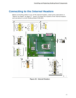
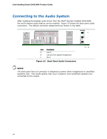
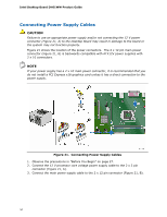
Installing and Replacing Desktop Board Components Chassis Intrusion Header Figure 18, C shows the location of the chassis intrusion header. This header can be connected to a mechanical switch on the chassis to detect if the chassis cover is removed. This switch should be in the open position when the chassis cover is installed and closed when the cover is removed. Table 7 shows the pin assignments and signal names for the chassis intrusion header. Table 7. Chassis Intrusion Header Signal Names Pin Description 1 Intruder# 2 Ground TPM Header The TPM header is shown in Figure 18, D. Table 8 shows the pin assignments and signal names for the TPM header. Table 8. TPM Header Signal Names Pin Signal Name Pin 1 CK_33M_TPM_DIP 2 3 LFRAME# 4 5 PLTRST# 6 7 LAD3 8 9 +3.3 V 10 11 LAD0 12 13 No connection 14 15 +3.3 VSB 16 17 Ground 18 19 LPCPD# 20 Signal Name Ground Key (no pin) No connection LAD2 LAD1 Ground No connection TPM_SERRQ TPM_CLKRUN# No connection 45
-
 1
1 -
2
-
3
-
4
-
5
-
6
-
7
-
8
-
9
-
10
-
11
-
12
-
13
-
14
-
15
-
16
-
17
-
18
-
19
-
20
-
21
-
22
-
23
-
24
-
25
-
26
-
27
-
28
-
29
-
30
-
31
-
32
-
33
-
34
-
35
-
36
-
37
-
38
-
39
-
 40
40 -
 41
41 -
 42
42 -
 43
43 -
 44
44 -
 45
45 -
 46
46 -
 47
47 -
 48
48 -
 49
49 -
 50
50 -
51
-
52
-
53
-
54
-
55
-
56
-
57
-
58
-
59
-
60
-
61
-
62
-
63
-
64
-
65
-
66
-
67
-
68
-
69
-
70
-
71
-
72
-
73
-
74
-
75
-
76
-
77
-
78
 |
 |
