Intel BLKDH61WWB3 Product Guide - Page 46
Front Panel Header, Serial Header, Table 9. Front Panel Header Signal Names
 |
View all Intel BLKDH61WWB3 manuals
Add to My Manuals
Save this manual to your list of manuals |
Page 46 highlights
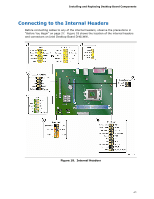
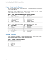
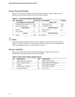
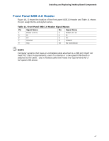
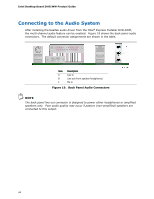
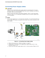
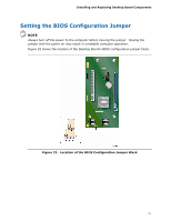
Intel Desktop Board DH61WW Product Guide Front Panel Header Figure 18, E shows the location of the front panel header. Table 9 shows the pin assignments and signal names for the front panel header. Table 9. Front Panel Header Signal Names Pin Description In/Out Pin Description Hard Disk Drive Activity LED Power LED 1 Hard disk LED pull-up to +5 V Out 2 Front panel LED+ 3 Hard disk active LED Out 4 Front panel LED- Reset Switch On/Off Switch 5 Ground 6 Power switch 7 Reset switch In 8 Ground Power Not Connected 9 Power Out 10 No pin In/Out Out Out In NOTE When connecting individual wires from your chassis front panel to the front panel header, be sure to observe the connection polarity. Positive wires are usually solid color and negative wires are usually white or striped. Serial Header Figure 18, F shows the location of the serial header. Table 10 shows the pin assignments and signal names for the serial header. Table 10. Serial Port Header Signal Names Pin Signal Name Pin Signal Name 1 DCD (Data Carrier Detect) 3 TXD# (Transmit Data) 5 Ground 7 RTS (Request To Send) 9 RI (Ring Indicator) 2 RXD# (Receive Data) 4 DTR (Data Terminal Ready) 6 DSR (Data Set Ready) 8 CTS (Clear To Send) 10 Key (no pin) 46
-
 1
1 -
2
-
3
-
4
-
5
-
6
-
7
-
8
-
9
-
10
-
11
-
12
-
13
-
14
-
15
-
16
-
17
-
18
-
19
-
20
-
21
-
22
-
23
-
24
-
25
-
26
-
27
-
28
-
29
-
30
-
31
-
32
-
33
-
34
-
35
-
36
-
37
-
38
-
39
-
40
-
 41
41 -
 42
42 -
 43
43 -
 44
44 -
 45
45 -
 46
46 -
 47
47 -
 48
48 -
 49
49 -
 50
50 -
 51
51 -
52
-
53
-
54
-
55
-
56
-
57
-
58
-
59
-
60
-
61
-
62
-
63
-
64
-
65
-
66
-
67
-
68
-
69
-
70
-
71
-
72
-
73
-
74
-
75
-
76
-
77
-
78
 |
 |
