Intel BLKDP965LTCK Product Specification - Page 21
Integrator's Note
 |
UPC - 200001254772
View all Intel BLKDP965LTCK manuals
Add to My Manuals
Save this manual to your list of manuals |
Page 21 highlights
Product Description Figure 3 illustrates the memory channel and DIMM configuration. NOTE The DIMM0 sockets of both channels are blue. The DIMM1 sockets of both channels are black. Figure 3. Memory Channel and DIMM Configuration # INTEGRATOR'S NOTE Regardless of the memory configuration used (dual channel, single channel, or flex mode), DIMM 0 of Channel A must always be populated. This is a requirement of the ICH8 Manageability Engine feature. 21
-
 1
1 -
2
-
3
-
4
-
5
-
6
-
7
-
8
-
9
-
10
-
11
-
12
-
13
-
14
-
15
-
 16
16 -
 17
17 -
 18
18 -
 19
19 -
 20
20 -
 21
21 -
 22
22 -
 23
23 -
 24
24 -
 25
25 -
 26
26 -
27
-
28
-
29
-
30
-
31
-
32
-
33
-
34
-
35
-
36
-
37
-
38
-
39
-
40
-
41
-
42
-
43
-
44
-
45
-
46
-
47
-
48
-
49
-
50
-
51
-
52
-
53
-
54
-
55
-
56
-
57
-
58
-
59
-
60
-
61
-
62
-
63
-
64
-
65
-
66
-
67
-
68
-
69
-
70
-
71
-
72
-
73
-
74
-
75
-
76
-
77
-
78
-
79
-
80
-
81
-
82
-
83
-
84
-
85
-
86
-
87
-
88
-
89
-
90
-
91
-
92
-
93
-
94
 |
 |

Product Description
21
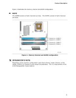
Figure 3 illustrates the memory channel and DIMM configuration.
±
NOTE
The DIMM0 sockets of both channels are blue.
The DIMM1 sockets of both channels
are black.
Figure 3.
Memory Channel and DIMM Configuration
INTEGRATOR’S NOTE
Regardless of the memory configuration used (dual channel, single channel, or flex
mode), DIMM 0 of Channel A must always be populated.
This is a requirement of the
ICH8 Manageability Engine feature.