Intel BOXD945PAWLK Product Specification - Page 55
Front Panel USB Connectors, INTEGRATOR'S NOTES, 8.2.6, Front Panel IEEE 1394a Connectors
 |
UPC - 735858174039
View all Intel BOXD945PAWLK manuals
Add to My Manuals
Save this manual to your list of manuals |
Page 55 highlights
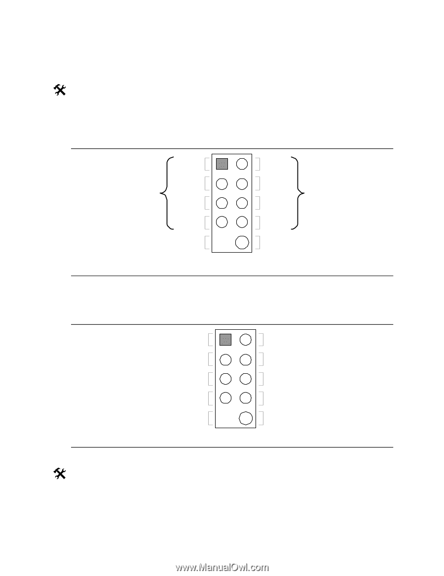
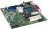
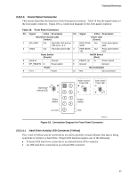
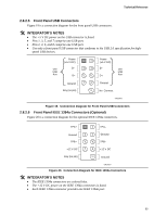
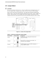
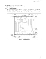
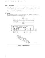
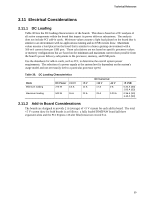
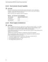
Technical Reference 2.8.2.5 Front Panel USB Connectors Figure 19 is a connection diagram for the front panel USB connectors. # INTEGRATOR'S NOTES • The +5 V DC power on the USB connector is fused. • Pins 1, 3, 5, and 7 comprise one USB port. • Pins 2, 4, 6, and 8 comprise one USB port. • Use only a front panel USB connector that conforms to the USB 2.0 specification for high- speed USB devices. Power (+5 V DC) One D− USB Port D+ 1 2 3 4 5 6 Power (+5 V DC) D− One USB D+ Port Ground 7 8 Ground Key (no pin) 10 No Connect OM15963 Figure 19. Connection Diagram for Front Panel USB Connectors 2.8.2.6 Front Panel IEEE 1394a Connectors (Optional) Figure 20 is a connection diagram for the optional IEEE 1394a connectors. TPA+ 1 2 TPA− Ground TPB+ +12 V DC 3 4 5 6 7 8 Ground TPB− +12 V DC Key (no pin) 10 Ground OM16107 Figure 20. Connection Diagram for IEEE 1394a Connectors # INTEGRATOR'S NOTES • The IEEE 1394a connectors are colored blue. • The +12 V DC power on the IEEE 1394a connectors is fused. • Each IEEE 1394a connector provides one IEEE 1394a port. 55
-
 1
1 -
2
-
3
-
4
-
5
-
6
-
7
-
8
-
9
-
10
-
11
-
12
-
13
-
14
-
15
-
16
-
17
-
18
-
19
-
20
-
21
-
22
-
23
-
24
-
25
-
26
-
27
-
28
-
29
-
30
-
31
-
32
-
33
-
34
-
35
-
36
-
37
-
38
-
39
-
40
-
41
-
42
-
43
-
44
-
45
-
46
-
47
-
48
-
49
-
 50
50 -
 51
51 -
 52
52 -
 53
53 -
 54
54 -
 55
55 -
 56
56 -
 57
57 -
 58
58 -
 59
59 -
 60
60 -
61
-
62
-
63
-
64
-
65
-
66
-
67
-
68
-
69
-
70
-
71
-
72
-
73
-
74
-
75
-
76
-
77
-
78
-
79
-
80
-
81
-
82
 |
 |