Intel BOXDX58SO Product Guide - Page 51
Alternate Front Panel Power LED Header, S/PDIF Connector
 |
View all Intel BOXDX58SO manuals
Add to My Manuals
Save this manual to your list of manuals |
Page 51 highlights
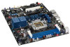
Installing and Replacing Desktop Board Components Alternate Front Panel Power LED Header Figure 27, H shows the location of the alternate front panel power LED header. Pins 1 and 3 of this header duplicate the signals on pins 2 and 4 of the front panel header. If your chassis has a three-pin power LED cable, connect it to this header. Table 12 shows the pin assignments and signal names for the alternate front panel power LED header. Table 12. Alternate Front Panel Power LED Header Signal Names Pin Description 1 Front panel green LED 2 No pin 3 Front panel yellow LED In/Out Out Out S/PDIF Connector Figure 27, J shows the location of the S/PDIF connector. This connector can be used with HDMI video cards that do not work with the HD Audio Link header (see Figure 27, B). Table 13 shows the pin assignments and signal names for the S/PDIF connector. Table 13. S/PDIF Connector Signal Names Pin Description 1 Vcc 2 S/PDIF Out 3 Ground 51
-
 1
1 -
2
-
3
-
4
-
5
-
6
-
7
-
8
-
9
-
10
-
11
-
12
-
13
-
14
-
15
-
16
-
17
-
18
-
19
-
20
-
21
-
22
-
23
-
24
-
25
-
26
-
27
-
28
-
29
-
30
-
31
-
32
-
33
-
34
-
35
-
36
-
37
-
38
-
39
-
40
-
41
-
42
-
43
-
44
-
45
-
 46
46 -
 47
47 -
 48
48 -
 49
49 -
 50
50 -
 51
51 -
 52
52 -
 53
53 -
 54
54 -
 55
55 -
 56
56 -
57
-
58
-
59
-
60
-
61
-
62
-
63
-
64
-
65
-
66
-
67
-
68
-
69
-
70
-
71
-
72
-
73
-
74
-
75
-
76
-
77
-
78
-
79
-
80
-
81
-
82
-
83
-
84
-
85
-
86
 |
 |
